
User Manual

5
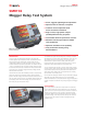
SMRT36
Megger Relay Test System
Battery Simulator
The SMRT36 with the P (Plus) option includes a battery simulator
with a variable DC output voltage ranging from 5 to 250 Volts at
100 Watts, 4 Amps max, providing capability to power up relays
with redundant power supplies. Voltage output is controlled via
the Smart Touch-View Interface, or through AVTS software. The
SMRT36 with the N option does not include a battery simulator.
Waveform Generation
Each output channel can generate a variety of output waveforms
such as: DC; sine wave; sine wave with percent harmonics at various
phase angles; half waves; square waves with variable duty cycles;
exponential decays; periodic transient waveforms from digital fault
recorders, relays with waveform recording capability or EMTP/
ATP programs, which conform to the IEEE C37.111 COMTRADE
standard format.
Metering
Measured output quantities such as AC Amperes, AC Volts, DC
Volts or DC Amperes, and Time may be simultaneously displayed
on the large, color TFT LCD touch screen. The AC and DC outputs
display the approximate voltage/current output prior to initiation of
the outputs. All accuracies stated are from 10 to 100% of the range
at 50/60Hz.
AC Voltage Amplitude
Accuracy: ±0.05 % reading + 0.02 % range typical,
±0.15 % reading + 0.05 % range maximum
Resolution: .01
Measurements: AC RMS
Ranges: 30, 150, 300V
AC Current Amplitude
Accuracy: ±0.05 % reading + 0.02 % range typical,
±0.15 % reading + 0.05 % range maximum
Resolution: .001/.01
Measurements: AC RMS
Ranges: 30, 60A
DC Voltage Amplitude
Accuracy: 0.1% range typical,
0.25% range maximum
Resolution: .01
Measurements: RMS
Ranges: 30, 150, 300V
DC Current Amplitude
Accuracy: ±0.05 % reading + 0.02 % range typical,
±0.15 % reading + 0.05 % range maximum
Resolution: .001/.01
Measurements: RMS
Ranges: 30A
Frequency
The output modules provide a variable frequency output with the
following ranges and accuracy.
Ranges
DC
0.001 to 1000.000 Hz
Output amplifiers can provide transient signals with a range of
DC to 10 kHz for transient playback using COMTRADE files.
Resolution*: .0001/.001 Hz
Frequency Accuracy:
2.5 ppm typical
25 ppm 0° to 50° C, at 50/60 Hz Maximum
Total Harmonic Distortion
Less than 0.1% typical, 2% maximum at 50/60 Hz
Timer
The Timer-Monitor Input is designed to monitor and time-tag
inputs, like a sequence of events recorder. In addition, the binary
input controls enable the user to perform logic AND/OR functions,
and conditionally control the binary output relay to simulate circuit
breaker, trip, reclose and carrier control operation in real-time. The
Timer function displays in Seconds or Cycles, with the following
range and resolution:
Seconds: 0.0001 to 99999.9
(Auto Ranging)
Cycles: 0.01 to 99999.9
(Auto Ranging)
Accuracy: ±0.001% of reading, typical. ±2 least significant digit,
±0.005% of reading from 0 to 50° C maximum
Binary Input – Start/Stop/Monitor Gate
To monitor operation of relay contacts or trip SCR, continuity light
is provided for the input gate. Upon sensing continuity the lamp will
glow. In addition to serving as wet/dry contacts the Binary Inputs
may be programmed to trigger binary output sequence(s).
Input Rating: up to 300 V AC/DC
Binary Output Relays
SMRT36 has independent, galvanically isolated, output relay
contacts to accurately simulate relay or power system inputs to
completely test relays removed from the power system. The binary
output simulates normally open / normally closed contacts for
testing breaker failure schemes. The binary output can be configured
to change state based on binary input logic.
High Current Output Relays: The first two VIGEN Modules have
1 each and the P option add 2 more.
AC Rating: 400 V max., Imax: 8 amps, 2000 VA max.
DC Rating: 300 V max., Imax: 8 amps, 80 W
Response Time: <10ms
High Speed Output Relays: SMRT36 P Option adds 2
AC/DC Rating: 400 V peak, Imax: 1 amp
Response Time: <1ms typical