
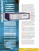
User guide

Once a CNR calibration has been performed, the ratio can
be changed using the internal precision attenuator to vary
the noise power without degrading accuracy. The output
noise power level is factory calibrated at a 0 dB attenuator
setting and is displayed in dBm/Hz.
Every front panel operation except instrument on/off is
programmable, and the user can create up to nine test
routines that can run automatically under program con-
trol. These routines can include delay times and loops, and
can be executed manually or via bus control. The routines
are easily written using the program key, and information
on the display guides the user through the next steps.
Applications:
• C/N Ratio Testing
• E
b
/N
o
Testing
• AWGN
• CCITT G.95
• SONET
• Data regenerators
• Multiplexers
• Hard disk drives
13
To order call 201-261-8797
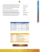
OPTIONS
Option Number Description
PNGopt01 SMA female input and output
PNGopt02 75 ohms input and output impedance
PNGopt03 230 VAC, 50 Hz
PNGopt04 Switch including up to 5 noise sources
PNGopt05 RS232 in addition to standard IEEE-488 interface
PNGopt06 127 dB signal attenuator in 1 dB steps
PNGopt07 DC coupled signal path (6 dB RF Loss)
PNG7000 SERIES
MODEL FREQUENCY OUTPUT CHARACTERISTICS
RANGE POWER (dBm) Vrms dBm/Hz FLATNESS(dB)
PNG7105 1 MHz - 10 MHz +3 0.316 -67 ±0.25
PNG7107 10 MHz - 100 MHz +3 0.316 -77 ±0.25 / 40 MHz
PNG7108 10 MHz - 500 MHz +3 0.316 -84 ±0.25 / 40 MHz
PNG7109 10 MHz - 1 GHz +3 0.316 -87 ±0.25 / 40 MHz
PNG7110 10 MHz - 1.5 GHz +3 0.316 -89 ±0.25 / 40 MHz
PNG7111 1 GHz - 2 GHz +3 0.316 -87 ±0.25 / 40 MHz
PNG7112 10 MHz - 2 GHz +3 0.316 -87 ±0.25 / 40 MHz
PNG7000 SERIES
NOISE GENERATORS
Lab Windows Drivers available
from National Instruments
Rev Date 5/15/03