
User Manual
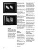

ACQUISITION MODES
DPO – Captures and displays complex
waveforms, random events, and subtle
patterns in actual signal behavior. By
acquiring up to 100M points/sec TDS 794D,
TDS 784D, TDS 754D, TDS 580D, TDS 540D
(50M points/sec; TDS 724D and TDS 520D)
DPOs are able to provide 3 dimensions of
signal information, in real-time; amplitude,
time, and the distribution of amplitude over
time. The DPX
™
Waveform Imaging Proces-
sor automatically selects record lengths
between 500 and 500,000 points and sam-
ple rate up to 1 GS/s, based on horizontal
time base setting, to optimize displayed
sample density.
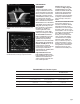
Peak Detect – High frequency and random
glitch capture. Captures glitches of 1 ns
using acquisition hardware at all real-time
sampling rates.
Sample – Sample data only.
Envelope – Max/min values acquired over
one or more acquisitions.
Average – Waveform data from 2 to 10,000
(selectable) is averaged.
Hi –res – Vertical resolution improvement
and noise reduction on low-frequency signal
(e.g., 12-Bits typical).
FastFrame
™
Time Stamp – Acquisition
memory size segmentable with trigger rate
up to 80,000 per second from 50 to 5,000
points per frame (independent of the num-
ber of channels).
Single Sequence – Use RUN/STOP button
to capture a single triggered acquisition at a
time, which may be automatically saved to
NVRAM with AutoSave.
TRIGGER SYSTEM
Triggers – Main and delayed.
Main Trigger Modes – Auto, Normal, Single.
Delayed Trigger – Delayed by time, events,
or events and time.
Time Delay Range – 16 ns to 250 s.
Events Delay Range – 1 to 9,999,999 events.
External Rear Input – ≥1.5 kΩ ; Max input
voltage is ±20 V (DC + peak AC).
TRIGGER TYPES
EDGE (Main and Delayed) –
Conventional level-driven trigger. Positive or
negative slope on any channel or rear panel
auxiliary input. Coupling selections: DC, AC,
noise reject, HF reject, LF reject.
LOGIC (Main) –
PATTERN: Specifies a logical combination
(AND, OR, NAND, NOR) of the four input
channels (high, low, don’t care). Trigger
when pattern stays true or false for a speci-
fied time.
STATE: Any logical pattern of channels 1, 2,
and 3 (AUX1 on 2-CH products) plus a
clock edge on channel 4 (AUX2 on 2-CH
products). Triggerable on rising or falling
clock edge.
SETUP/HOLD: Trigger on violations of both
setup time and hold time between clock and
data which are on two input channels.
page 4
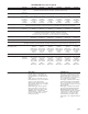
Characteristics
TDS 500D/700D Series Electrical Characteristics
TDS 794D TDS 784D TDS 754D TDS 724D TDS 580D TDS 540D TDS 520D
Bandwidth 2 GHz*
5
1 GHz*
1
500 MHz*
2
500 MHz*
2
1 GHz*
4
500 MHz*
2
500 MHz*
2
# Channels 4 4 4 2 + 2 aux. 4 4 2 + 2 aux.
# Samplers 4 4 4 2 4 4 2
Max Real-time Sample Rate
1 channel 4 GS/s 4 GS/s 2 GS/s 2 GS/s 4 GS/s 2 GS/s 2 GS/s
2 channels 2 GS/s 2 GS/s 2 GS/s 1 GS/s 2 GS/s 2 GS/s 1 GS/s
3-4 channels 1 GS/s 1 GS/s 1 GS/s NA 1 GS/s 1 GS/s NA
Equivalent-time Sample Rate 250 GS/s max. 250 GS/s max. 100 GS/s max. 100 GS/s max. 250 GS/s max. 100 GS/s max. 100 GS/s max.
Maximum Record Length
1 channel 50 K 50 K 50 K 50 K 50 K 50 K 50 K
(opt. 1M: 500 K, (opt. 1M: 500 K, (opt. 1M: 500 K, (opt. 1M: 250 K, (opt. 1M: 500 K, (opt. 1M: 500 K, (opt. 1M: 250 K,
opt. 2M: 8 M) opt. 2M: 8 M) opt. 2M: 8 M) opt. 2M: 4 M) opt. 2M: 8 M) opt. 2M: 8 M) opt. 2M: 4 M)
2 channels 50 K 50 K 50 K 50 K 50 K 50 K 50 K
(opt. 1M: 250 K, (opt. 1M: 250 K, (opt. 1M: 250 K, (opt. 1M: 130 K, (opt. 1M: 250 K, (opt. 1M: 250 K, (opt. 1M: 130 K,
opt. 2M: 4 M) opt. 2M: 4 M) opt. 2M: 4 M) opt. 2M: 2 M) opt. 2M: 4 M) opt. 2M: 4 M) opt. 2M: 2 M)
3-4 channels 50 K 50 K 50 K NA 50 K 50 K NA
(opt. 1M: 130 K, (opt. 1M: 130 K, (opt. 1M: 130K, – (opt. 1M: 130 K, (opt. 1M: 130 K, –
opt. 2M: 2 M) opt. 2M: 2 M) opt. 2M: 2 M) – opt. 2M: 2 M) opt. 2M: 2 M) –
Max Sample Rate Window*
3
2 ms 2 ms 4 ms 2 ms 2 ms 4 ms 2 ms
Display NuColor
™
NuColor
™
NuColor
™
NuColor
™
monochrome monochrome monochrome
Display Display Display Display
*
1
In 50 Ω mode: 5 mV/div: 750 MHz, 2 mV/div: 600 MHz, 1 mV/div: 500 MHz. Make phrasing same as Reduce the upper bandwidth frequencies by 5 MHz for
each
degree C above 30 °C.
*
2
In 50 Ω mode: 1 mV/div: 450 MHz. Reduce the upper bandwidth frequencies by 2.5 MHz for each degree C above 30 °C.
*
3
Single-channel operating at full sample rate and maximum record length (Opt. 2M).
*
4
≥ 10 mV/div in 50 Ω mode.
*5 reduce for upper bandwidth frequency by 10 MHz °C above 30°C.