
Owner manual

5
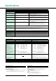
Item Voltage V
15/30/60/150/300/600V
Input resistance: Approx. 2 MΩ, Input capacitance:
Approx. 13 pF
Peak voltage of 2.8 kV or rms of 2.0 kV, whichever is less
Peak voltage of 2.0 kV or rms of 1.5 kV, whichever is less
Peak voltage of 1.5 kV or rms of 1.0 kV, whichever is less
600 Vrms (with the output connector protective cover used) CAT II, 400 Vrms (with the output connector protective cover removed) CAT II
With voltage input terminals short and current input terminals open, 50/60 Hz, -80 dB or more (±0.01% of range or less)
Reference value: 50 kHz max., ±{(maximum range rating)/(range rating) × 0.001 × 1% of rng} or less (voltage range, 0.5 A to 20 A current range)
±{(maximum range rating)/(range rating) × 0.0002 × 1% of rng} or less (WT200, 5 mA to 200 mA range)
0.01% or more. The unit of "f" is kHz.
Binding posts
Simultaneous conversion of voltage and current inputs, Resolution: 12 bits, Maximum conversion rate: Approx. 26 µs (at approx. 38 kHz)
Range can be selected manually, automatically, or by communication control.
Range up: When the measured value exceeds 110% of the rated range or the peak value exceeds approximately 300% of the rated range
Range down: When the measured value becomes less than 30% of the rated range and the peak value is less than approximately 300% of the subordinate range
One of the following modes can be set (manually or by communication control): RMS: True RMS measurements for both voltage and current;
V MEAN: Rectified mean calibrated to an RMS sine wave measurement for voltage, and true RMS measurement for current; DC: Mean value measurement for both voltage and current
Resistance voltage divider
Current A
Shunt input
Direct input: 5/10/20/50/100/200 mA (for WT200 only)
0.5/1/2/5/10/20 A (for WT200/WT130)
External input (optional): 2.5/5/10 V or 50/100/200 mV
Direct input: Approx. 6 mΩ + approx. 0.1 µH (0.5 to 20 A, WT200/WT130),Approx. 500 mΩ (5 mA to
200 mA, WT200) External input: 2.5/5/10 V - approx. 100 kΩ or 50/100/200 mV - approx. 20 kΩ
0.5 to 20 A (WT200/WT130): Peak current of 450 A or rms of 300 A, whichever is less
5 to 200 mA (WT200): Peak current of 150 A or rms of 100 A, whichever is less
For external input, the peak value is equal to or less than 10 times range.
0.5 to 20 A (WT200/WT130): Peak current of 150 A or rms of 40 A, whichever is less
5 to 200 mA (WT200): Peak current of 30 A or rms of 20 A, whichever is less
For external input, the peak value is equal to or less than 10 times range.
0.5 to 20 A (WT200/WT130):
Peak current of 100 A or rms of 25 A, whichever is less (WT200)
Peak current of 100 A or rms of 30 A, whichever is less (WT130)
5 to 200 mA (WT200): Peak current of 30 A or rms of 20 A, whichever is less
For external input, the peak value is equal to or less than 5 times range.
Direct input: Large binding posts, External input: Safety terminals
Input circuit type
Rated inputs (range)
Equipment loss (input resistance)
Instantaneous maximum allowable
input for one cycle, 20 ms
Instantaneous maximum allowable
input for 1 sec.
Continuous maximum allowable input
Continuous maximum common-mode
voltage (at 50/60 Hz input)
Common-mode rejection ratio at 600 Vrms
between input terminal and case
Input terminals
A/D conversion
Range switching
Automatic range switching
Measurement mode switching
Floating input
Input
Notes: Direct input and external sensor input of current cannot be used simultaneously. When the input is switched for use, note that the ± terminals are shared.
Specifications
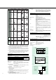
Item Voltage/current
DC:
10Hz % f , 45Hz :
45Hz % f % 66Hz :
66Hz , f % 1kHz :
1kHz , f % 10kHz :
10kHz , f % 20kHz
Reference value
20kHz
, f %
50kHz :
*DC: ±0.2% of range is added if the 0.5/1 A range is selected (WT130 only)
For the input range of 10% to 110%, the above specified accuracy is valid. For the input range of 110% to 130%, the above specified reading accuracy increased by 0.5 times is added to the accuracy.
The above specified reading accuracy increased by 0.5 times is added to the accuracy (within 3 months after calibration).
±0.03% of range/°C at 5 to 18°C and 28 to 40°C
4 times/s
± (0.2 % of rdg + 0.2 % of rng)
*
± (0.3 % of rdg + 0.2 % of rng)
± (0.15 % of rdg + 0.1 % of rng)
± (0.3 % of rdg + 0.2 % of rng)
± (0.2 % of rdg + 0.3 % of rng)
± {(0.05 × )% of rdg}
± (0.5 % of rdg + 0.5 % of rng)
± [{0.15 × (f-10)}% of rdg]
± (0.5 % of rdg + 0.5 % of rng)
± [{0.15 × (f-10)}% of rdg]
Active power
DC:
10Hz % f , 45Hz :
45Hz % f % 66Hz :
66Hz , f % 1kHz :
1kHz , f ^ 10kHz :
10kHz , f % 20kHz :
Reference value
20kHz
, f % 50kHz :
*DC: ±0.2% of range is added if the 0.5/1 A range is selected (WT130 only)
cosϕ = 0
45 Hz % f % 66 Hz: Add ±0.25% of range to display accuracy.
Reference data (50 kHz max.): ±{(0.23 + 0.4 x f)% of rng}
1 > cosϕ > 0
Add the value of the influence of cosϕ = 0 times tanϕ to display accuracy.
Note that ϕ represents the phase angle between voltage and current.
± (0.3 % of rdg + 0.3 % of rng)
*
± (0.5 % of rdg + 0.3 % of rng)
± (0.2 % of rdg + 0.1 % of rng)(WT200)
± (0.25 % of rdg + 0.1 % of rng)(WT130)
± (0.5 % of rdg + 0.3 % of rng)
± (0.3 % of rdg + 0.5 % of rng)
± {(0.08 × f)% of rdg}
± (0.8 % of rdg + 0.8 % of rng)
± [{0.19 × (f-10)}% of rdg]
± (0.8 % of rdg + 0.8 % of rng)
± [{0.25 × (f-10)}% of rdg]
Method
Frequency range
Crest factor
Display accuracy
Accuracy
(within 3 months after calibration)
Conditions:
Temperature: 23 ± 5°C
Humidity: 30 to 75% R.H.
Supply voltage: 100 V ± 5%
Input waveform: Sine wave
Common-mode voltage: 0 V DC
Filter: ON at 200 Hz or less
Scaling: OFF
After CAL is performed, accuracy is
assured by YOKOGAWA calibration
system.
Note: The unit of "f" in accuracy
expressions is kHz.
Effect of power factor
Note: The unit of "f" in accuracy
expressions is kHz.
Effective input range
Accuracy (
within 12 months after calibration
)
Temperature coefficient
Display update rate
Digital sampling method and summation averaging method
DC, 10 Hz to 50 kHz
"3" at rated input
Measurement Functions
Note: "rdg" means reading and "rng" means range.
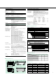
Communication
Either GP-IB or RS-232-C is selected.
GP-IB
Electrical and mechanical specifications: IEEE Std. 488-1978 (JIS C 1901-1987)
Functional specifications: SH1, AH1, T5, L4, SR1, RL1, PR0, DC1, DT1, C0
Protocol: IEEE Std. 488.2-1987
Code used: ISO (ASCII) code
Address: 0 to 30 talker/listener addresses are settable.
RS-232-C
Transmission mode: Start-stop synchronization
Baud rate: 75, 150, 300, 600, 1200, 2400, 4800, 9600 bps
Frequency Measurement
Input: One of V1, V2, V3, A1, A2, and A3 is selected.
Operating principle: Reciprocal counting method
Frequency range: 10 Hz to 50 kHz
Accuracy: ±(0.1% of rdg + 1 digit)
Minimum input is more than 30% of rated range.
When an input frequency is less than 200 Hz, FILTER must be ON to obtain the speci-
fied accuracy.
Minimum input frequency is more than 20% of frequency measurement range.