
Owner manual

6
Note 1:The apparent power (VA), reactive power (var), power factor (PF), and phase angle
(deg) measurements in this instrument are computed digitally from the voltage, cur-
rent, and active power. If the input is non-sinusoidal, the measured values may differ
from those obtained with instruments employing different measurement principles.
Note 2:When the current or voltage is less than 0.5% of the range, VA and var will be dis-
played as 0, and PF/deg will be displayed as an error.
Note 3:The Lead and Lag are displayed for V and A input at 50% or more of the rated range.
The detected lead/lag accuracy is ±5 degrees over the frequency range of 20 Hz to 2
kHz.
Note 4:In a Σvar calculation, the var value of each phase is calculated as a negatively signed
value when the phase of the current input is advanced with respect to the voltage
input, and is calculated as a positively signed value when the phase is lagging.
* The WT200 can provide 5-digit display (note that the resolution is 20000).
PF
i
=
i=1, 2, 3
Σ PF
=
PF
i
=
i=1, 3
Σ PF
=
Σ W
ΣVA
ϕ
i
=cos
–1
()
i=1, 3
Σϕ
=cos
–1
()
var
i
= (VA
i
)
2
–W
i
2
i=1, 3
Σ var
=var
1
+var
3
VA
i
=V
i
× A
i
i=1, 2, 3
Σ VA
=
×
(VA
1
+VA
2
+VA
3
)
ϕ
i
=cos
–1
()
i=1, 3
Σϕ
=cos
–1
()
Σ W
Σ VA
Σ W
Σ VA
PF
i
=
i=1, 3
Σ PF
=
VA
i
=V
i
× A
i
i=1, 3
Σ VA
=
×
(VA
1
+VA
3
)
Active power
(W)
Apparent power
(VA)
Reactive
(var)
Power factor
(PF)
Phase angle
(deg)
1-phase
2-wire
W
i
i=1, 3
Σ W
=W
1
+W
3
VA
i
=V
i
× A
i
i=1, 3
Σ VA
=VA
1
+VA
3
var
i
= (VA
i
)
2
–W
i
2
i=1, 3
Σ var
=var
1
+var
3
3-phase
3-wire
(two-
power-
meter
method)
W
i
i=1, 3
Σ W
=W
1
+W
3
3
2
3-phase
3-wire
(three-
power-
meter
method)
var
i
= (VA
i
)
2
–W
i
2
i=1, 2, 3
Σ var
=var
1
+var
3
3-phase
4-wire
W
i
i=1, 2, 3
Σ W
=W
1
+W
2
+W
3
var
i
= (VA
i
)
2
× W
i
2
i=1, 2, 3
Σ var
=var
1
+var
2
+var
3
VA
i
=V
i
× A
i
i=1, 2, 3
Σ VA
=VA
1
+VA
2
+VA
3
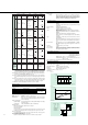
Computing
range
Display
resolution
Computing
accuracy
(relative to the
value calculated
from measured
values)
W
i
i=1, 2, 3
(Note that W
2
does not have
physical
meaning.)
Σ W
=W
1
+W
3
W
i
VA
i
PF
i
=
i=1, 2, 3
Σ PF
=
W
i
VA
i
–1 to 0 to 1
± 1.000*
0.0005
W
i
VA
i
W
i
VA
i
W
i
VA
i
3
3
W
i
VA
i
Σ W
ΣVA
Σ W
ΣVA
Σ W
ΣVA
1-phase
3-wire
W
i
VA
i
W
i
VA
i
Σ W
Σ VA
Σ W
Σ VA
cos
–1
()
W
VA
W
VA
(VA)
2
–W
2
VA=V × A
W
Depends on
selected V and
A ranges.
±0.005% of VA
range
Same as apparent
power (var ^ 0)
±0.005% of var range
Depends on
selected V
and A ranges.
9999* 9999* 9999*
—
–180 to 0 to 180
± 180.0
Resolution
(power factor
±0.0005)
ϕ
i
=cos
–1
()
i=1, 2, 3
Σϕ
=cos
–1
()
ϕ
i
=cos
–1
()
i=1, 2, 3
Σϕ
=cos
–1
()
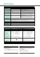
Computation
Display Function
Display type: 7-segment LED
Number of displays: 3
V, A, W, VA, var (each element), elapsed integrating time
V, A, W, PF, deg (each element), % (contents ratio in %, THD)
V, A, W, V · AHz, ±Wh, ±Ah (each element), Vpk, Apk, MATH
Display
A
B
C
V, A, W: 9999
Wh, Ah: 999999
V, AHz : 9999
Displayed value
Maximum Reading
* In the WT200 either 4 or 5 digits for display can be selected.
Unit: m, k, M, V, A, W, VA, var, Hz, h±, deg, %
Display update rate: 4 times/s
Response time: Approx. 0.5 s (time for displayed value to settle within specified
accuracy of final value after step change from 0% to 10% or 100%
to 0% of rated range)
Display scaling function
Significant digits: Selected automatically according to significant digits in the voltage
and current ranges
Setting range: 0.001 to 9999 (WT200), 0.001 to 1000 (WT130)
Averaging function:
Either of the following two algorithms can be selected:
Exponential averaging
Moving averaging
Response can be set; for exponential averaging, the attenuation constant can be selected
and for moving averaging, the number of averages (N) can be set to 8, 16, 32, or 64.
Peak over-range display
The alarm LED will light up if the rms value is greater than 140% of the range or the
peak value is greater than 300% of the range.
MAX hold function (WT200 only)
Capable of storing the maximum values for V, A, W, VA, var, Vpk, and Apk.
MATH function
Method: When the DISPLAY C function is set to MATH, the efficiency
(WT130 only) and input crest factor can be measured, and the
results of four arithmetic operations of measured values can be
displayed on Displays A and B as well as the average active power
after time-conversion of integrating power (WT200 only).
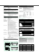
Integrator Function
Display resolution: Depending on integrated value, the resolution will be changed (for
WT200).
Depending on elapsed time value, the resolution will be changed
(for WT130).
Maximum display: –99999 to 999999 MWh/MAh
Modes: Standard integration mode (timer mode)
Continuous integration mode (repeat mode)
Manual integration mode
Timer: When the timer is set, integration will be stopped automatically.
Setting range: 000 h:00 min:00 sec to 10000 h:00 min:00 sec
(WT200)
Setting range: 000 h:00 min to 999 h:59 min (WT130)
(When set time is 0, the manual integration mode is automatically
selected.)
Type: Standard type Adds active power and current value of normal
measurements.
Advanced type (WT200 only) Integrates active power and current
values in short time intervals, not depending on input signal pe-
riod.
Count overflow: If the integration count exceeds 999999 MWh/MAh or -999999
MWh/MAh, integration stops and the elapsed time is held on the
display.
Accuracy: ± (display accuracy + 0.2% of rdg)
Timer accuracy: ±0.02%
Remote control: Start, stop, and reset can be remotely controlled by an external
contact signal. Note that this is available only when the /DA4 or /
DA12 option has been installed.
Internal Memory Function
Measurement data Number of data that can be stored: WT200 (253421): 600 blocks
WT130 (253502): 300 blocks
WT130 (253503): 200 blocks
Writing interval: 250 ms, or 1 s to 99 h:59 min:59 sec
Reading interval: 250 ms, or 1 s to 1 h (both intervals can be set in
units of second)
Panel setup information: Four-pattern information can be written/read.
D/A Converter (Optional)
Output voltage: ±5 V DC FS (approx. ±7.5 V maximum) at rated value or range
Number of output channels
: 12 when the /DA12 option is installed; 4 when the /DA4 option is
installed
Output data selection: Can be selected for each channel.
Accuracy: ± (display accuracy + 0.2% of range)
Update rate: Same as display update rate
Temperature coefficient: ±0.05% of f.s./°C
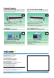
Output format
D/A output
7.5V
5.0V
2.5V
0.5V
0
10Hz 100Hz 1kHz 10kHz
Displayed value50kHz
Frequency
Integration
D/A output
7.0V
5.0V
0
t0 Integration time
140% input of the rated value
Rated value input
t0: Rated value setting time
Other items
0V
–100%–140%
–5.0V
–7.0V
–7.5V
5.0V
7.0V
7.5V
140%100%
D/A output
Displayed value
Displayed value
140%
100%
0%
–100%
–140%
Output
7.0V
5.0V
0V
–5.0V
–7.0V
For PF and deg, a
value between ±5 and
±7 V will not be
output. If an error
occurs, the output will
be approx. 7.5 V.