
Owner manual

7
External Input (Optional)
Either /EX1 or /EX2 can be selected as a voltage-output-type current sensor.
/EX1: 2.5/5/10 V
/EX2: 50/100/200 mV
Specifications: See the “Input” item.
Comparator Output (Optional)
Output method: Normally open and normally closed relay contact outputs (in pairs)
Number of output channels and channel setup: 4 (settable for each channel)
Contact capacity: 24 V/0.5 A
D/A output (4 channels): See the “D/A Converter (Optional)” item.
External Control and Input Signals (only when the D/A or /CMP option has been installed)
External control and input/output signals:
EXT-HOLD, EXT-TRIG, EXT-START, EXT-STOP, EXT-RESET,
INTEG-BUSY
Note: That the /DA4 or /DA12 option must be installed.
Note: Only EXT-HOLD and EXT-TRIG are available when the / CMP
option has been installed.
Input level: TTL negative pulse
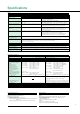
General Specifications
EMI standard: EN55011 Group 1 Class A
EN50082-2: 1995
Safety standards: EN61010-1
Overvoltage Category II
Pollution degree 2
Warm-up time: Approx. 30 min.
Operating temperature and humidity range: 5 to 40°C, 20 to 80% R.H. (no condensation)
Storage temperature: –25 to 60°C (no condensation)
Operating altitude: 2000 m or less
Insulation resistance: Between voltage input terminals and case
Between current input terminals and output terminals
Between voltage input terminals and current input terminals
Between voltage input terminals of each element
Between current input terminals of each element
Between voltage input terminals and power plug
Between current input terminals and power plug
Between case and power plug
The above values must be 50 MΩ or more at 500 V DC.
Withstanding voltage: Between voltage input terminals and case
Between current input terminals and output terminals
Between voltage input terminals and current input terminals
Between voltage input terminals of each element
Between current input terminals of each element
Between voltage input terminals and power plug
Between current input terminals and power plug
The above values must be 3700 V for 1 minute at 50/60 Hz.
Between case and power plug: 1500 V for 1 minute at 50/60 Hz
Power supply: Any power supply voltage between 100 and 240 V; frequency: 50/
60 Hz
Vibration test conditions: Sweep test - Frequency: 8 to 150 Hz sweep, all three directions
for 1 minute
Endurance test - Frequency: 16.7 Hz, all three directions; ampli-
tude of 4 mm for 2 hr
Impact conditions: Impact test: Acceleration of 490 m/s
2
, all three directions
Free-fall test - Height:100 mm, 1 time for each of four sides
Power consumption:
WT200: 35 VA max., WT130: 50 VA max. (for power supply of 240 V)
WT200:25 VA max., WT130: 32 VA max. (for power supply of 100
V)
External dimensions: WT200:Approx. W × H × D: 213 × 88 × 350 (mm) (not including
projections)
8-3/8 × 3-1/2 × 13-3/4 (inch) (not including projections)
WT130:Approx. W × H × D: 213 × 132 × 350 (mm) (not including
projections)
8-3/8 × 5-3/16 × 13-3/4 (inch) (not including projections)
Weight: WT200:Approx. 3.0 (kg), 6.6 (lbs.)
WT130:Approx. 5.0 (kg), 11.0 (lbs.)
Accessories: Power cord: UL/CSA, VDE, SAA or BS standard, 1 pc.
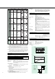
■ External Dimension
250
213
179
8819
73
23
356
213
13
132
23
356
20
Unit: mm
Harmonic Analysis Function (Optional)
Method: Synchronization to the fundamental frequency by using a phase
locked loop (PLL) circuit
Frequency range: Fundamental frequency between 40 Hz and 440 Hz
Display resolution: 9999 (WT130), 9999 or 20000 (WT200)
Items analyzed: V, A, W, deg (WT200); V1, V2, V3, A1, A2, A3, W1, W2, W3, deg1,
deg2, deg3 (WT130), each harmonic component, total Vrms, total
Arms, total active power, PF of the fundamental wave, phase-angle
of fundamental wave, total harmonic distortion ratio in %, and con-
tents ratio in %
Note that simultaneous analysis can be made for one specified input mode.
Sampling speed/method:
The sampling speed depends on the fundamental frequency to be input:
Input
frequency
range
Sampling
frequency
Window
up to the n'th
harmonic
Order
40% f<70Hz
70% f<130Hz
130% f<250Hz
250% f% 440Hz
f×512Hz
f×256Hz
f×128Hz
f×64Hz
1 period of f
2 period of f
4 period of f
8 period of f
50
50
50
30
FFT number of points: 512 points FFT
FFT calculation accuracy:32 bits
Window: Rectangular window
Display update interval: Approx. 3 sec.
Accuracy: ±0.2% of range is added to the normal display accuracy.
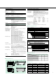
■ Model and Suffix Codes
253421
Power cord
Optional
features
-D
-F
-R
-Q
/C1
/C2
/EX1
/EX2
/HRM
/DA4
/CMP
WT200, 1-input element model
UL/CSA standard
VDE standard
SAA standard
BS standard
GP-IB communication function
RS-232-C communication function
External input 2.5/5/10 V
External input 50/100/200 mV
Harmonic analysis function
4-channel D/A output
Comparator & D/A, each of 4 channels
Model Description
Suffix Code
Select one.
Select one.
Select one.
Note: The WT200 communication feature cannot be modified or provided later after
delivery of the product.
253502
253503
Interface
Supply voltage
Power cord
Optional features
-C1
-C2
-0
-D
-F
-R
-J
/EX1
/EX2
/HRM
/DA12
/CMP
WT130, 2-input element model
WT130, 3-input element model
GP-IB communication function
RS-232-C communication function
Any power supply voltage between 100 and 240 V
UL/CSA standard
VDE standard
SAA standard
BS standard
External input 2.5/5/10 V
External input 50/100/200 mV
Harmonic analysis function
12-channel D/A output
Comparator & D/A, each of 4 channels
Model Description
Suffix Code
Select one.
Select one.
Select one.
■ Wiring and Model
Single-phase, 2-wire
Single-phase, 3-wire
Three-phase, 3-wire (2-power-meter method)
Three-phase, 3-wire (3-power-meter method)
Three-phase, 4-wire
253421
u
-
-
-
-
253502
u
u
u
-
-
253503
u
u
u
u
u
Wiring
Model
■ Accessories
Model or Part Number
751533-E2
751533-J2
751534-E2
751534-J2
751533-E3
751533-J3
751534-E3
751534-J3
Specifications
Single-mounted WT200 for EIA
Single-mounted WT200 for JIS
Dual-mounted WT200 for EIA
Dual-mounted WT200 for JIS
Single-mounted WT130 for EIA
Single-mounted WT130 for JIS
Dual-mounted WT130 for EIA
Dual-mounted WT130 for JIS
Order Quantity
1
1
1
1
1
1
1
1
Name
Rack-mount kit
Rack-mount kit
Rack-mount kit
Rack-mount kit
Rack-mount kit
Rack-mount kit
Rack-mount kit
Rack-mount kit