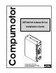
Installation Guide COM 1 COM 2 ENCODER I/O Rx Tx D GN D x+ L R SH Rx V +5 D Tx+ GN Tx D Rx N G Tx LD SH D L SH D GN ZZ+ BB+ AA+ V +5 D GNM HOG NE S O P -A G TRG-B TR T-A OUD GN UT C PV +5 T-P OUP IN X-P AUI/O V_ 4 610 R E IV DR XE DE IN TA ZE ER W PO P EP EM LT ST R T U E FA OV OR T K O M OC RL TAP E T ER IN NT A CE A+ A- MOTOR LIMITS H RT EA B+ P BB ER NT CE TA K OC RL TE IN or ot m Co 95-132 VAC 50/60 Hz AC POWER pu m PROGRAMMABLE I/O Compumotor ZETA6104 Indexer/
User Information ! WARNING ! 6000 Series products are used to control electrical and mechanical components of motion control systems. You should test your motion system for safety under all potential conditions. Failure to do so can result in damage to equipment and/or serious injury to personnel.
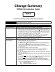
Change Summary ZETA6104 Installation Guide Rev B September 1997 The following is a summary of the primary technical changes to this document. This book, p/n 88-014782-02B, supersedes 88-014782-02A and 88-014782-01B. Revision B Change Wiring diagrams (series/parallel connections) for RSxxx-xxNPS and RSxxx-xxC10 motor options have been corrected Ð see page 9.
LVD and EMC Installation Guidelines The ZETA6104 is in compliance with the Low Voltage Directive (72/23/EEC) and the CE Marking Directive (93/68/EEC) of the European Community. When installed according to the procedures in the main body of this installation guide, the ZETA6104 may not necessarily comply with the Low Voltage Directive (LVD). To install the ZETA6104 so that it is LVD compliant, refer to supplemental installation instructions provided in Appendix C.
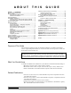
ABO U T T H I S Chapter 1. Installation What You Should Have (ship kit) ........................................................... 2 Before You Begin ..................................................................................... 2 Recommended Installation Process ............................................. 2 Electrical Noise Guidelines ........................................................... 2 General Specifications ............................................................................
LVD Installation Guidelines The ZETA6104 is in compliance with the Low Voltage Directive (72/23/EEC) and the CE Marking Directive (93/68/EEC) of the European Community. When installed according to the procedures in the main body of this installation guide, the ZETA6104 may not necessarily comply with the Low Voltage Directive (LVD). To install the ZETA6104 so that it is LVD compliant, refer to supplemental installation instructions provided in Appendix C.
1 CHAP T E R ONE Installation IN THIS CHAPTER ¥ ¥ ¥ ¥ ¥ ¥ ¥ ¥ ¥ ¥ ¥ Product ship kit list Things to consider before you install the ZETA6104 General specifications table Optional pre-installation alterations - DIP switch settings Ð motor current, device address, autobaud feature - Changing the COM 2 port from RS-232C to RS-485 Mounting the ZETA6104 Connecting all electrical components (includes specifications) Testing the installation Matching the motor to the ZETA6104 Motor mounting and coupling guideli
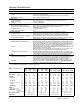
What You Should Have (ship kit) Part Name Part Number ZETA6104 standard product (with ship kit).............. ZETA6104 Ship kit: 120VAC power cord.......................................... 44-014768-01 Motor connector ................................................ 43-008755-01 (ZETA series motors are factory wired with a motor connector) Wire jumpers: Qty. 3....................................... 44-015142-01 Qty. 1.......................................
General Specifications Parameter Specification Power AC input .................................................................... 95-132VAC, 50/60Hz, single-phase (refer to page 18 for peak power requirements, based on the motor you are using) Status LEDs/fault detection...................................... Refer to Diagnostic LEDs on page 34 Environmental Operating Temperature ..........................................
Pre-installation Adjustments Factory Settings May Be Sufficient (if so, skip this section): ¥ Device address is set to zero (if daisy-chaining you can automatically establish with the ADDR command). ¥ Serial communication method is RS-232C. DIP Switch Settings Ð Motor Current, Address, Autobaud Move the Cover Top View of ZETA6104 CAUTION Do not set switches 6-11 to ON at the same time. This invokes a factory test mode in which the ZETA6104 executes a motion sequence upon power up.
Changing the COM 2 Connector from RS-232 to RS-485 RS-232C Users RS-485 (optional) The ZETA6104Õs COM 2 port is factory configured for RS-232C communication (use the left-hand pin descriptions). If you do not need to use RS-485 communication, you may ignore this section and proceed to the Mounting instructions. RS-232 (factory default) Remove the two retainer screws. (one on the top of the chassis, one on the bottom of the chassis) Heatsink Slide the chassis forward, then away from the heat sink.
Mounting the ZETA6104 Before you mount the ZETA6104 Check the list below to make sure you have performed all the necessary configuration tasks that require accessing internal components (DIP switches, potentiometers, and jumpers). You may, however, be able to adjust DIP switches and pots after mounting, if you allow access to the top of the ZETA6104 chassis. ¥ Select motor current (DIP switches). If you ordered a ZETA motor with your system (e.g.
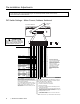
Electrical Connections To install the ZETA6104 so that it is LVD compliant, refer also to the supplemental instructions in Appendix C. Appendix D provides guidelines on how to install the ZETA6104 in a manner most likely to minimize the ZETA6104Õs emissions and to maximize the ZETA6104Õs immunity to externally generated electromagnetic interference.
Serial Communication RS-232C Connections RS-232C Daisy-Chain Connections* Unit 0 COM 1 Tx Rx GND COM 2 Serial Port Connection 9-Pin COM Port: 25-Pin COM Port: Rx Tx GND Pin 2 (Rx) Pin 3 (Tx) Pin 5 (GND) Pin 2 (Tx) Pin 3 (Rx) Pin 7 (GND) Tx Rx GND Rx Tx GND SHLD +5V Rx+ GND RxÐ Rx Tx+ Tx TxÐ SHLD GND Unit 1 Rx Tx GND SHLD Unit 2 Rx Tx GND SHLD Rx Tx GND SHLD Daisy Chain to a Computer or Terminal Unit 0 Unit 1 Rx Tx GND SHLD Rx Tx GND Unit 2 Rx Tx GND SHLD Rx Tx GND SHLD Stand-Alone Da
Motor (ZETA and OS/RS motors only) ZETA, OS and RS Motors Specifications Ð see page 3. Speed/Torque curves Ð see page 10. Considerations for series & parallel wiring Ð see page 10. Current settings Ð see page 4. Dimensions Ð see page 24. Cable extension Ð see table below. ZETA & RSxxx-xxC10 motors include a rubber boot for safety. Motor Connector MOTOR INTERLOCK ACENTERTAP A+ AÐ EARTH B+ BÐ BCENTERTAP INTERLOCK WARNING: Remove AC power before connecting or disconnecting the motor.
Selecting Series or Parallel Motor Wiring Zeta Motor Curves oz-in (N-m) 75 = Torque = Power oz-in (N-m) Power watts (hp) ZETA57Ð51 (0.53) O & R Motor Curves = Torque = Power Power watts (hp) OS2HB 100 (0.70) Parallel 91 (0.12) Parallel 80 (0.56) (0.42) Torque Torque 60 Series 45 (0.32) 30 (0.21) Parallel 129 (0.18) Series 68 (0.09) Parallel (3.01A pk) 60 (0.43) 40 (0.28) Series (1.51A pk) 15 (0.11) 0 0 20 30 Speed-RPS 10 Torque oz-in (N-m) 125 (0.88) 100 (0.70) 75 (0.
End-of-Travel and Home Limit Inputs NOTES ¥ CAUTION: Use either the on-board +5V terminal or an external power supply to power the AUX-P pull-up resistor (using both will damage the ZETA6104). ¥ Motion will not occur until you do one of the following: - Install end-of-travel (POS & NEG) limit switches. - Disable the limits with the LH¯ command (recommended only if load is not coupled). - Change the active level of the limits with the LHLVL command.
Encoder CONNECTIONS & INTERNAL SCHEMATICS ENCODER Connector Internal Schematic Max. Cable Length is 100 feet. Use 22 AWG wire. Shield Shield Shield Ground Black Black Z Channel Ð Orange/White (n/a) Z Channel + Orange Blue B Channel Ð Green/White (n/a) B Channel + Green Brown A Channel Ð Brown/White (n/a) A Channel + Brown White +5VDC Red Red SHLD GND Isolated Ground ZZ+ Same Circuit B- as A Channel B+ AA+ +5V Chassis Ground +1.
Trigger Inputs ENCODER Connector TRG-A/B connected to GND (normally-open switches). Internal Schematic SHLD GND ZZ+ BB+ AA+ +5V The active level (default is active low) can be changed with the INLVL command. These inputs are like the general-purpose inputs on the 50-pin header.
General-Purpose Programmable Inputs & Outputs VM50 ADAPTOR Ñ for screw-terminal connections Color stripe (pin #1) 1 PROGRAMMABLE I/O 2-Foot Cable (provided with VM50) 50 Pin outs on the VM50 are identical to the pin outs for the 50-pin connectors (only if the cable is connected as illustrated). Color stripe (pin #1) The VM50 snaps on to any standard DIN rail.
INPUT CONNECTIONS Ñ Connecting to electronic devices such as PLCs Connection to a Sinking Output Device Electronic Device ZETA6104 GND ISO GND +5V The output should be able to sink at least 1mA of current. Pulled up to +5V (sourcing) Out 5-24 Volts +5VDC IN-P Output Input Connection Ground Ground Connection 6.8 KW 74HCxx 47 KW PROGRAMMING TIP Connecting to a sinking output? Set the inputÕs active level to low with the INLVL command (¯ = active low).
OUTPUT CONNECTIONS (includes OUT-A) Ñ for electronic devices such as PLCs Connection to a Sinking Input (active high) External Supply (up to 24VDC) Electronic Device + Connection to a Sourcing Input (active low) ZETA6104 Ð External Supply (up to 24VDC) Electronic Device GND + Ð ZETA6104 GND ISO GND ISO GND +5V +5V +5VDC +5VDC OUT-P Input Output Connection Ground Ground Connection V+ OUT-P Input Output Connection Ground Ground Connection 4.
THUMBWHEEL CONNECTIONS Ñ for entering BCD data Connection to the Compumotor TM8 Module TM8 Thumbwheel Module + 1 2 3 4 5 6 7 8 +5 GND I5 I4 I3 I2 I1 O5 O4 O3 O2 O1 ZETA6104 Programmable Input #1 Programmable Input #2 Programmable Input #3 Programmable Input #4 Programmable Input #5 Pin #49 (+5VDC) Pin #48 (GND) Programmable Output #1 Programmable Output #2 Programmable Output #3 Optional Sign Bit Connection to your own Thumbwheel Module Input #9 (sign) Input #8 MSB Input #7 Input #6 Input #5 LS
RP240 Remote Operator Panel RP240 Connections when using RS-485 RP240 Back Plane Rx Tx GND SHLD +5V Rx+ GND RxÐ Rx Tx+ Tx TxÐ SHLD GND COM 2 GND HOM NEG POS TRG-A TRG-B OUT-A GND P-CUT +5V OUT-P IN-P AUX-P V_I/O I/O In addition, you will have to issue these commands to configure the ZETA6104 to communicate successfully with the RP240 connected to COM 1 and with RS-485 connected to COM 2.
Lengthening I/O Cables Bear in mind that lengthening cables increases noise sensitivity. (The maximum length of cables is ultimately determined by the environment in which the equipment will be used.) If you lengthen the cables, follow the precautions below to minimize noise problems. ¥ Use a minimum wire size of 22 AWG. ¥ Use twisted pair shielded cables and connect the shield to a SHLD terminal on the ZETA6104. Leave the other end of the shield disconnected.
Testing the Installation WARNING This test procedure allows you to control I/O and produce motion. Make sure that exercising the I/O will not damage equipment or injure personnel. We recommend that you leave the motor uncoupled from the load, but if you have coupled the load to the motor, make sure that you can move the load without damaging equipment or injuring personnel.
Connections Test Procedure Response Format (left to right) End-of-travel and Home Limits NOTE: If you are not using end-of-travel limits, issue the Disable Limits (LH¯) command and ignore the first two bits in each response field. TLIM response: bit 1= POS (positive travel) limit bit 2= NEG (negative travel) limit bit 3 = HOM (home) limit 1. Enable the hardware end-of-travel limits with the LH3 command. 2. 3. 4. 5. 6. 7. Close the end-of-travel switches and open the home switch.
Matching the Motor to the ZETA6104 (OPTIONAL) Due to slight manufacturing variations, each motor has its own particular characteristics. In the procedure below, you will adjust three potentiometers (pots), to match your ZETA6104 to your specific motor. You will also select the best current waveform to use with your motor. If you purchased a ZETA6104 and ZETA motor system (not applicable to OS and RS motors), the ZETA6104 and the ZETA motor were matched to each other at the factory.
Step 3 Run your motor at the resonant speed listed in the Offset Adjust column. Vary the speed slightly until you find the resonance point. To initiate motion, type these commands (followed by a carriage return) to the ZETA6104 from the terminal emulator: MC1 (This command makes the motion run continuously until you issue a !S command.) Vn (This command sets the velocity to n . For example, V4.66 sets the velocity to 4.66 rps.) GO (This command initiate motion.
Mounting & Coupling the Motor WARNINGS ¥ ¥ ¥ Improper motor mounting and coupling can jeopardize personal safety, and compromise system performance. Never disassemble the motor; doing so will cause contamination, significant reduction in magnetization, and loss of torque. Improper shaft machining will destroy the motorÕs bearings, and void the warranty. Consult a factory Applications Engineer (see phone number on inside of front cover) before you machine the motor shaft.
R Series, 23 Frame End Bell Construction (NPS) 4 x ¯0.218 (5.46) thru equally spaced on a ¯3.875 (98.43) B.C. 3.38 (85.85) 0.003 (0.077) -ALmax. 2 x 45¡ Model RS31BRS32BRS32B- Lmax L2 NPS 3.62 (n n91.95) 2.87 (n n72.90) NPS 4.77 (121.16) 4.02 (102.11) NPS 6.05 (153.67) 5.30 (134.62) ¯2.875 + - 0.002 (73.025 + - 0.051) 0.003 (0.077) -A- + 0.0000 ¯0.3750 - 0.0005 + 0.000) (9.53 - 0.013) 0.002 (0.051) -A- 1.25 (31.75) 0.06 (1.52) 0.18 (4.57) L2 Standard Front Shaft Configurations 0.75 (19.
Optimizing System Performance (OPTIONAL) The ZETA6104 is equipped with three damping circuits that minimize resonance and ringing, and thus enhance stepper performance: The ZETA6104 automatically switches between the damping circuits, based upon the motorÕs speed. ¥ Anti-Resonance Ð General-purpose damping circuit. The ZETA6104 ships from the factory with anti-resonance enabled (see DAREN command). No configuration is necessary.
Step 2 Establish appropriate inductance and static torque settings. If you ordered a ZETA6104 and a ZETA motor together as a ÒsystemÓ, these settings were made at the factory (OS and RS motors may not be ordered as a ÒsystemÓ). Use the DMTIND command to set the inductance, and use the DMTSTT command to set the static torque (see table below). The DMTIND and DMTSTT values are automatically saved in battery-backed RAM.
Step 4 Make a baseline move with active damping disabled. This is your baseline move. Notice the sound, amount of motor vibration, etc. This move shows how your system operates with anti-resonance enabled, and active damping disabled. Each time you adjust the DACTDP setting (in steps 5-7), you will compare results against this baseline move. 1. Issue the DACTDP¯ command to disable active damping. 2. Make a move that is representative of your application, with similar velocity and acceleration.
Configuring Electronic Viscosity (EV) Before You Start ¥ If you configured active damping (see procedure above), leave the DACTDP setting set at the value you chose. You do not need to disable active damping while you configure EV. ¥ Couple the motor to the load (see pages 24-25 for details). EV must be configured under the normal mechanical operating conditions for your application. ¥ Record the DELVIS command setting.
Record Your SystemÕs Configuration You may wish to record your configuration information in the chart below.
Set-up Program Example Assumptions: The ZETA6104 is used with a Zeta83-93 motor wired in series. RS-232C is connected to the COM 1 serial port. An RP240 is connected to the COM 2 serial port.
WhatÕs Next? By now, you should have completed the following tasks, as instructed earlier in this chapter: 1. 2. 3. 4. 5. 6. 7. 8. 9. Review the general specifications Ñ see page 3 Perform configuration/adjustments, as necessary Ñ see pages 4-5 Mount the ZETA6104 Ñ see page 6 Connect all electrical system components Ñ see pages 7-19 Supplemental installation instructions for LVD-compliance are provided in Appendix C.
2 CHAP T E R T WO Troubleshooting IN THIS CHAPTER ¥ Troubleshooting basics: - Reducing electrical noise - Diagnostic LEDs - Test options - Technical support ¥ Solutions to common problems ¥ Resolving serial communication problems ¥ Product return procedure
Troubleshooting Basics When your system does not function properly (or as you expect it to operate), the first thing that you must do is identify and isolate the problem. When you have accomplished this, you can effectively begin to resolve the problem. The first step is to isolate each system component and ensure that each component functions properly when it is run independently. You may have to dismantle your system and put it back together piece by piece to detect the problem.
Common Problems & Solutions NOTE: Some software-related causes are provided because it is sometimes difficult to identify a problem as either hardware or software related. Problem Communication (serial) not operative, or receive garbled characters Cause 1. Improper interface connections or communication protocol 2. COM port disabled 3. In daisy chain or multi-drop, the unit may not be set to proper address Direction is reversed. 1.
Troubleshooting Serial Communication Problems General Notes ¥ Power up your computer or terminal BEFORE you power up the ZETA6104. ¥ Make sure the serial interface is connected as instructed on page 8. Shield the cable to earth ground at one end only. The maximum RS-232 cable length is 50 feet (15.25 meters). ¥ RS-232: Handshaking must be disabled. Most software packages allow you to do this.
Problem/Remedy Table (continued) Problem Remedy (based on the possible causes) Garbled Characters ¥ Verify setup: 9600 baud (range is 19200-1200Ñsee AutoBaud, page 4), 8 data bits, 1 stop bit, no parity; RS-232: Full duplex; RS-485: Half duplex (change internal jumper JU6 to position 1). ¥ RS-485: Transmission line not properly terminated. See page 5 for internal DIP switch and jumper settings.
Appendix A Resonance, Ringing & DampingÑ Discussion & Theory In this appendix we will discuss resonance and ringing in step motors. This information will help you configure the ZETA6104Õs damping featuresÑantiresonance, active damping, and electronic viscosity. All step motors have natural resonant frequencies, due to the nature of their mechanical construction. Internally, the rotor acts very similarly to a mass suspended on a springÑit can oscillate about its commanded position.
response to a sudden change that we impose on the system, such as ÒAccelerate to VelocityÓ or ÒStop.Ó Electronic Viscosity Ð Provides passive damping at lower speeds. The ZETA6104 ships with electronic viscosity disabled. You must use the DELVIS command to enable electronic viscosity, and optimize it for a specific application (see procedure on page 29). Several problems are associated with ringing.
Anti-Resonance (AR) Anti-resonance monitors the ZETA6104Õs motor terminals, and looks at power exchange between the ZETA6104 and motor. From this, it extracts information about error in rotor position caused by resonance or ringing. It modifies the internal motor current command to correct for the error. Anti-resonance is a general-purpose circuit. It corrects rotor position error, without knowledge about the systemÑwhether the motor is large or small, or the system inertia is high or low.
Appendix B Using Non-Compumotor Motors We recommend that you use Compumotor motors with the ZETA6104. If you use a nonCompumotor motor, it must meet the following requirements: ¥ ¥ ¥ ¥ ¥ ¥ Inductance: 0.5 mH minimum; 5.0 to 50.0 mH recommended range; 80.0 mH maximum. A minimum of 500VDC high-pot insulation rating from phase-to-phase and phase-to-ground. The motor must be designed for use with a bipolar drive (no common center tap). The motor must not have riveted rotors or stators.
8-Lead Motor Because of the complexity involved in phasing an 8-lead motor, you must refer to the manufacturerÕs motor specification document. You can configure the 8-lead motor in parallel or series. Using the manufacturerÕs specifications, label the motor leads as shown in the next drawing. Terminal Connections After you determine the motorÕs wiring configuration, connect the motor leads to the ZETA6104Õs 9-pin MOTOR connector according to the appropriate diagram below.
Direction of Motor Rotation The procedures above do not determine the direction of motor shaft rotation. To find out which direction the shaft turns, you must power up your system and command motion. If the shaft turns in the opposite direction than you desire, exchange the motor leads connected to A+ and AÐ to reverse the direction of rotation. CAUTION Motor shaft rotation may be opposite than you expect. Do not connect a load to the shaft until you first determine the direction of shaft rotation.
Appendix C LVD Installation Instructions For more information about the Low Voltage Directive (LVD), see 73/23/EEC and 93/68/EEC, published by the European Economic Community (EEC). Environmental Conditions Pollution Degree: The ZETA6104 is designed for pollution degree 2. Installation Category: The ZETA6104 is designed for installation category II.
Mechanical Table of Graphic Symbols & Warnings Installing in an Enclosure: The ZETA6104 must be installed within an enclosure. The enclosureÕs interior must not be accessible to the operator. The enclosure should be opened only by skilled or trained service personnel. The following symbols may appear in this manual, and may be affixed to the products discussed in this manual.
Appendix D EMC Installation Guidelines General Product Philosophy The ZETA6104 was not designed originally for EMC compliance. Therefore, it will require specific measures to be taken during installation. The ultimate responsibility for ensuring that the EMC requirements are met rests with the systems builder. It is important to remember that for specific installations, the full protection requirements of the EMC Directive 89/336/EEC need to be met before the system is put into service.
cable (this allows the braid to continue to the cable connector), be careful not to damage the braid. Snap the P-clip over the exposed braid, and adjust for a tight fit. Secure the clip to the designated ground with a machine screw and lock washer. The use of brass or other inert conductive metal P-clip is recommended. Cover any exposed bare metal with petroleum jelly to resist corrosion. P-Clip Remove outer jacket only do not cut braid Figure 2.
At the drive end, run the motor cable down to the mounting panel, expose a short length of braiding and anchor to the panel with a P-clip. The ZETA Series require a safety earth connection to the motor (see green and yellow striped wire in Figure 4) Ñ take this from the stud or bus bar. Run the safety earth lead alongside the motor lead. Note that the motor cable should be kept away from I/O cables carrying control signals.
Motor Cable (braided-screen) Motor Safety Earth (grn/yel) CommEncoder COM 2 Limits Cable ENCODER I/O Cable LIMITS I/O Programmable I/O Cable 04 61 E IV R DR XE DE IN TA ZE ER W PO P EP EM LT ST R T U E FA OV OR T CK MO LO P R TA TE IN NTER A CE A+ A- MOTOR Rx Tx D GN D x+ L R SH Rx V +5 D Tx+ GN Tx D Rx N G Tx LD SH D L SH D GN ZZ+ B B+ AA+ V +5 D GNM HOG NE S PO -A G TRG-B TR T-A OUD GN UT C P V +5 T-P OUP IN X-P AU COM 1 Braided-screen Cables H RT EA B+ P BB ER NT CE TA
I N D E X 3rd harmonic 23 4-lead motor (non-Compumotor) wiring 43 6-lead motor (non-Compumotor) wiring 43 5V power supply connections (see page for connection item, like P-CUT, Encoder, etc.) load limit 3 8-lead motor (non-Compumotor) wiring 44 6000user@cmotor.
DIP switch settings address 4 autobaud feature 4 bias & termination resistors 5 motor current 4 disassembling the ZETA6104 5 DMTIND (inductance) command 27 part of setup program 30 DMTSTT (static torque) command 27 part of set-up program 30 drive resolution 35 drive/motor matching 22 DRPCHK command 18 part of set-up program 30 DWAVEF (waveform) command 23 part of set-up program 30 E e-mail address for feedback i ECHO 30 electrical noise 2, 34 EMC installation guidelines 49 suppressing 19 electronic viscosi
precautions installation 2 mounting 6 process of installation 2 product return procedure 37 programmable I/O connections & specs 14 testing 21 programming tools available 32 pulse cut-off (P-CUT) testing 21 R reference documentation i removing the ZETA6104 chassis 5 resistors, termination/bias calculating 8 selecting 5 resolution drive 35 encoder 12, 35 resonance 39 return procedure 37 ringing 39 rotor inertia, zeta & OS/RS motors 3 RP240, connections 18 testing 21 RS-232C (see serial communication) RS-485
ZETA6104 Indexer/Drive Automation Setup Connections ZETA, OS & RS MOTOR CONNECTIONS (see also pages 9 & 10) Series Connection Parallel Connection Rx Tx GND SHLD +5V GND Rx Tx SHLD COM 2 Refer to page 10 for instructions on wiring an RS motor that is ordered with the -C10 option or the -NPS option.