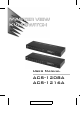
User Manual ACS-1208A ACS-1216A 2003-06-20
Note: This equipment has been tested and found to comply with the limits for a Class B digital device, pursuant to Part 15 of the FCC Rules. These limits are designed to provide reasonable protection against harmful interference in a residential installation. This equipment generates, uses and can radiate radio frequency energy, and if not installed and used in accordance with the instruction manual, may cause interference to radio communications.
ACS-1208A / ACS-1216A User Manual Packing List The complete ACS-1208A / ACS-1216A package consists of: M M M M M M 1 2 1 1 1 1 ACS-1208A or ACS-1216A KVM Switch Custom KVM Cable Sets (2L-5202P) Firmware Upgrade Cable Power Adapter Rack Mounting Kit User Manual Check to make sure that all the components are present and that nothing got damaged in shipping. If you encounter a problem, contact your dealer.
ACS-1208A / ACS-1216A User Manual Table of Contents 1. Introduction Overview . . . . . . . . . . . . . . Features . . . . . . . . . . . . . . . Hardware Requirements . . . . . . Console . . . . . . . . . . . . Computers . . . . . . . . . . . Cables . . . . . . . . . . . . . ACS-1208A Front View . . . . . . . ACS-1216A Front View . . . . . . . ACS-1208A / ACS-1216A Rear View . . . . . . . . . . . . . . . . . . . . . . . . . . . . . . . . . . . . . . . . . . . . . . . . . . . . . . . . . . . . . . .
ACS-1208A / ACS-1216A User Manual 4. OSD Operation OSD Operation . . . . . . . . . OSD Overview . . . . . . . OSD Navigation . . . . . . . OSD Main Screen Headings OSD Functions . . . . . . . . . . . . . . . . . . . . . . . . . . . . . . . . . . . . . . . . . . . . . . . . . . . . . . . . . . . . . . . . . . . . . . . . . . . . . . . . . . . . . . . . . . . . . . . . . . . . . . 4-1 4-1 4-3 4-3 4-4 . . . . . . . . . . . . . . . . . . . . . . . . . . . . . . . . . . . . . . . . . .
ACS-1208A / ACS-1216A User Manual About This Manual This User Manual is provided to help you get the most from your ACS-1208A / ACS-1216A system. It covers all aspects of installation, configuration and operation. An overview of the information found in the manual is provided below. Overview Chapter 1, Introduction, introduces you to the ACS-1208A / ACS1216A System. Its purpose, features and benefits are presented, and its front and back panel components are described.
ACS-1208A / ACS-1216A User Manual Conventions The following typographical conventions are used throughout this manual: M Bullet lists provide information, but not procedural steps. M Numbered lists represent procedures with sequential steps. M An indented typeface like the one below: Key information in indicates words and characters you key in. Unless otherwise mentioned, you can use either upper or lower case.
ACS-1208A / ACS-1216A User Manual Notes: viii 2003-06-20
Chapter 1. Introduction chapter introduces you to the ACS-1208A / ACS-1216A KVM Switch. Its This purpose, features and benefits are presented, and its front and back panel components are described. Overview The Master View ACS-1208A and ACS-1216A KVM Switches are control units that allow access to multiple computers from a single console (keyboard, mouse, and monitor).
ACS-1208A / ACS-1216A User Manual Your ACS-1208A / ACS-1216A investment is protected by an included Firmware Upgrade Utility. You can stay current with the latest improvements in functionality by downloading the latest firmware files from our website and using the utility to quickly and conveniently perform the upgrade. Setup is fast and easy; plugging cables into their respective ports is all that is entailed.
Introduction Features M A single console controls up to 8 (ACS-1208A) or 16 (ACS-1216A) computers M Daisy chain up to 31 additional units - control up to 512 computers from a single console M No software required - convenient computer selection via Hotkeys and intuitive OSD menus M Auto Scan feature for monitoring user-selected computers M Hot Pluggable - add or remove computers without having to power down the switch M Custom ASIC (patent pending) for increased reliability and enhanced performance M Auto-
ACS-1208A / ACS-1216A User Manual Hardware Requirements Console Computers M A VGA, SVGA, or Multisync monitor capable of the highest resolution that you will be using on any computer in the installation. M A PS/2 style mouse M A PS/2 style keyboard The following equipment must be installed on each computer: M A VGA, SVGA or Multisync card. M A 6-pin mini-DIN (PS/2 style) mouse port.
Introduction Cables Substandard cables may damage the connected devices or degrade overall performance. For optimum signal integrity and to simplify the layout, we strongly recommend that you use the high quality CS Custom Cable sets described below: Function CS Part Number KVM Switch to KVM Switch (Daisy Chaining) 2L-1700 - 0.6 m 2L-1701 - 1.8 m KVM Switch to Computer 2L-5201P - 1.2 m 2L-5202P - 1.8 m 2L-5203P - 3.0 m 2L-1700 / 2L-1701 2L-5201P / 5202P / 5203P Note: 1.
ACS-1208A / ACS-1216A User Manual ACS-1208A Front View 1 POWER 2 3 4 1. Port LEDs The Port LEDs provide status information about their corresponding CPU Ports. There is one pair of LEDs for each Port. The one on the left is the On Line LED; the one on the right is the Selected Port LED: M An On Line LED lights ORANGE to indicate that the computer attached to its corresponding port is up and running.
Introduction 3. Power LED The Power LED lights to indicate that the ACS-1208A is powered up and ready to operate. 4. Station ID LED The ACS-1208A’s Station ID is displayed here. If this is a Single Station installation (see p. 2-1), or the First Station on a Daisy Chained installation (see p. 2-2), the ACS-1208A has a Station ID of 01. On a Daisy Chained installation, the ACS-1208A auto-senses its position and displays the Station ID that corresponds to its place in the chain. (see Port ID Numbering, p.
ACS-1208A / ACS-1216A User Manual ACS-1216A Front View 1 POWER 2 3 4 1. Port LEDs The Port LEDs provide status information about their corresponding CPU Ports. There is one pair of LEDs for each Port. The one on the left is the On Line LED; the one on the right is the Selected Port LED: M An On Line LED lights ORANGE to indicate that the computer attached to its corresponding port is up and running.
Introduction 3. Power LED Lights to indicate that the ACS-1216A is powered up and ready to operate. 4. Station ID LED The ACS-1216A’s Station ID is displayed here. If this is a Single Station installation (see p. 2-1), or the First Station on a Daisy Chained installation (see p. 2-2), the ACS-1216A has a Station ID of 01. On a Daisy Chained installation, the ACS-1216A auto-senses its position and displays the Station ID that corresponds to its place in the chain. (see Port ID Numbering, p.
ACS-1208A / ACS-1216A User Manual ACS-1208A / ACS-1216A Rear View 1 3 4 5 2 7 6 1 3 4 5 6 2 7 1. Daisy Chain Ports When Daisy Chaining Units, the cables plug in here. The port on the left is the Chain In port; the one on the right is the Chain Out port. 2. CPU Port Section The cables that link to the computers plug in here. The shape of these connectors has been specifically modified so that only cables designed to work with this switch can plug in (see the Cables section on p.
Introduction 5. Firmware Upgrade Port The Firmware Upgrade Cable that transfers the firmware upgrade data from the administrator’s computer to the ACS-1208A / ACS-1216A (see p. 5-2), plugs into this RJ-11 socket. 6. Firmware Upgrade Recovery Switch During normal operation and while performing a fimware upgrade, this switch should be in the NORMAL position. See p. 5-8 for details about the use of this switch. 7.
ACS-1208A / ACS-1216A User Manual Notes: 1-12 2003-06-20
Chapter 2. Installation chapter explains how to connect up your installation — from a basic single This stage arrangement to a complete daisy chained configuration. Before you Begin 1. Make sure that power to all the devices you will be connecting up have been turned off. You must unplug the power cords of any computers that have the Keyboard Power On function. Otherwise, the switch will still receive power from the computers. 2.
ACS-1208A / ACS-1216A User Manual 3. Plug the power adapter cable into the Master View’s Power Jack, then plug the power adapter into an AC power source. 4. Turn on the power to the computers. Daisy Chaining To control even more computers, up to 31 additional switches can be daisy chained down from the first unit. As many as 512 computers can be controlled from a single console in a complete installation.
Installation 2. Use a daisy chain cable set (described in the Cables section, p. 1-5), to connect the Chain Out port of the parent switch to the Chain In port of the child switch (First Station Out to Second Station In, Second Station Out to Third Station In, etc.). Note: You cannot use the Chain In port of the First Station Master View, since it is the highest level parent. 3. Use KVM cable sets (described in the Cables section, p.
ACS-1208A / ACS-1216A User Manual 2-4 2003-06-20
Installation Hot Plugging The ACS-1208A / ACS-1216A supports hot plugging - components can be removed and added back into the installation by unplugging their cables from the ports without the need to shut the unit down. In order for hot plugging to work properly, however, the procedures described below must be followed: Switching Station Positions: You can switch station positions by simply unplugging from the old parent and plugging into a new one.
ACS-1208A / ACS-1216A User Manual Port ID Numbering Each CPU port on a Master View installation is assigned a unique Port ID. The Port ID is made up of two parts: a two-digit Station Number, and a two-digit Port Number: M The Station Number - reflects the switch’s position in the daisy chain sequence. This corresponds to the number displayed on the front panel Station ID LED. M The Port Number - reflects the port on the Station that the computer is connected to.
Chapter 3. Hotkey Operation chapter details the concepts and procedures involved in the Hotkey operation This of your ACS-1208A / ACS-1216A installation. Hotkey Port Access Hotkey port access allows you to provide KVM focus to a particular computer directly from the keyboard. The Master View ACS-1208A / ACS-1216A provides the following Hotkey port access features: M Selecting the Active Port M Auto Scanning M Skip Mode Switching Invoking Hotkey Mode All Hotkey operations begin by invoking Hotkey Mode.
ACS-1208A / ACS-1216A User Manual When Hotkey Mode is active: M The Caps Lock and Scroll Lock LEDs flash in succession. They stop flashing and revert to normal status when you exit Hotkey Mode. M A Command Line appears on the monitor’s screen. The command line prompt is the word Hotkey: and appears in yellow text on a blue background. Subsequent Hotkey information that you key in displays on this line, as well.
Hotkey Operation Auto Scanning Auto Scan automatically switches among all accessible CPU Ports at regular intervals, so that the operator can monitor their activity without having to switch among them manually. (See Scan/Skip Mode of the OSD F3 SET function, p. 4-7 for information regarding accessible ports.) Setting the Scan Interval: The amount of time Auto Scan dwells on each port is set with the Scan Duration setting of the OSD F3 SET function (see p. 4-7).
ACS-1208A / ACS-1216A User Manual Invoking Auto Scan: To start Auto Scanning, key in the following Hotkey combination: 1. Invoke Hotkey Mode (see p. 3-1). 2. Press [A]. You automatically exit Hotkey Mode, and enter Auto Scan Mode. The KVM focus switches among the accessible computers at regular intervals. While you are in Auto Scan Mode, note the following: M You can pause the scanning in order to keep the focus on a particular computer either by pressing P or with a Left Click of the mouse.
Hotkey Operation Skip Mode Skip Mode allows you to switch between computers in order to monitor them manually. Unlike Auto Scanning, which automatically switches after a fixed interval, you can dwell on a particular port for as long or as little as you like. To invoke Skip Mode, key in the following Hotkey combination: 1. Invoke Hotkey Mode (see p. 3-1). 2. Key in [Arrow] Where [Arrow] refers to one of the Arrow keys.
ACS-1208A / ACS-1216A User Manual Hotkey Beeper Control The Beeper (see Activate Beeper, p. 4-9) can be Hotkey toggled On and Off. To toggle the Beeper, key in the following Hotkey combination: 1. Invoke Hotkey Mode (see p. 3-1). 2. Press [B] After you press B, the Beeper toggles On or Off. The Command Line displays Beeper On or Beeper Off for one second; then the message disappears and you automatically exit Hotkey Mode.
Chapter 4. OSD Operation chapter provides a complete description of the procedures involved in the OSD This (On Screen Display) operation of your ACS-1208A / ACS-1216A installation. OSD Operation OSD Overview The On Screen Display (OSD) is a menu driven method to handle computer control and switching operations. All procedures start from the OSD Main Screen. To pop up the Main Screen, tap the [Scroll Lock] key twice.
ACS-1208A / ACS-1216A User Manual When you invoke the OSD, a screen similar to the one below appears: F1:GOTO F3:SET F2:LIST F4:ADM ADMINISTRATOR LIST:ALL SN PN QV 01 01 01 02 02 02 02 02 14 15 16 01 02 03 04 05 F5:SKP F6:BRC F7:SCAN X z F8:LOUT zz NAME ATEN INTL.CO. 1 ATEN INTL.CO. 2 ATEN INTL.CO. 3 FAX SERVER 1 FAX SERVER 2 WEB SERVER 1 WEB SERVER 2 MAIL SERVER 1 Note: 1. The diagram depicts the Administrator’s Main Screen.
OSD Operation OSD Navigation w To dismiss the menu, and deactivate OSD, Click the X at the upper right corner of the OSD Window; or press [Esc]. w To Logout, Click F8 at the top of the Main Screen, or press [F8]. w To move up or down through the list one line at a time, Click the Up and Down Triangle symbols (▲▼) or use the Up and Down Arrow Keys. If there are more list entries than what can appear on the Main Screen, the screen will scroll.
ACS-1208A / ACS-1216A User Manual OSD Functions OSD functions are used to configure and control the OSD. For example, you can: rapidly switch to any port; scan selected ports only; limit the list you wish to view; designate a port as a Quick View Port; create or edit a port name; or make OSD setting adjustments. To access an OSD function: 1. Either Click a Function Key field at the top of the Main Screen, or press a Function Key on the keyboard. 2.
OSD Operation F2 LIST: The LIST function lets you broaden or narrow the scope of which ports the OSD displays (lists) on the Main Screen. Many of the OSD functions only operate on the computers that have been selected for listing on the Main Screen with this function. The choices and their meanings are given in the table below: Choice Meaning ALL Lists all of the ports on the installation. QVIEW Lists only the ports that have been selected as Quick View Ports (see SET ACCESSIBLE PORTS, p. 4-10).
ACS-1208A / ACS-1216A User Manual F3 SET: This function allows the Administrator and each User to set up his own working environment. A separate profile for each is stored by the OSD and is activated according to the Username that is provided during Login. To change a setting: 1. Double Click it; or move the highlight bar to it, then press [Enter]. 2. After you select an item, a submenu with further choices appears.
OSD Operation (F3 SET: continued) Setting Function PORT ID DISPLAY MODE Selects how the Port ID is displayed: the Port Number alone (PORT NUMBER); the Port Name alone (PORT NAME); or the Port Number plus the Port Name (PORT NUMBER + PORT NAME). The default is PORT NUMBER + PORT NAME). SCAN DURATION Determines how long the focus dwells on each port as it cycles through the selected ports in Auto Scan Mode (see F7 SCAN, p. 4-14). Key in a value from 1 - 255 seconds, then press [Enter].
ACS-1208A / ACS-1216A User Manual F4 ADM: F4 is an Administrator only function. It allows the Administrator to configure and control the overall operation of the OSD. To change a setting Double Click it; or use the Up and Down Arrow Keys to move the highlight bar to it then press [Enter]. After you select an item, a submenu with further choices for you to select from appears. Double Click the choice you want, or move the Highlight Bar to it then press [Enter].
OSD Operation (F4 ADM: continued) Setting Function EDIT PORT NAMES To help remember which computer is attached to a particular port, every port can be given a name. This function allows the Administrator to create, modify, or delete port names. To Edit a port name: 1. Click the port you want, or use the Navigation Keys to move the highlight bar to it, then press [Enter]. 2. Key in the new Port Name, or modify/delete the old one. The maximum number of characters allowed for the Port Name is 12.
ACS-1208A / ACS-1216A User Manual (F4 ADM: continued) Setting SET QUICK VIEW PORTS Function This function lets the Administrator select which Ports to include as Quick View ports. w To select/deselect a port as a Quick View Port, Double Click the port you want, or use the Navigation Keys to move the highlight bar to it, then press [Enter]. w When a port has been selected as a Quick View Port, an arrowhead displays in the QV column of the LIST on the Main Screen to indicate so.
OSD Operation (F4 ADM: continued) Setting Function RESET STATION IDS If you change the position of one of the Stations in the daisy chain, the OSD settings will no longer correspond to the new situation. This function directs the OSD to rescan the Station positions of the entire installation and updates the OSD so that the OSD Station information corresponds to the new physical layout. Note: Only the Station Numbers get updated.
ACS-1208A / ACS-1216A User Manual F5 SKP: This function enables you to easily skip backward or forward switching the console focus from the currently active computer port to the previous or next available one. w The selection of computers to be available for Skip Mode switching is made with the Scan/Skip Mode setting under the F3 SET function (see p. 4-7).
OSD Operation F6 BRC: F6 is an Administrator only function. When this function is in effect, commands sent from the console are broadcast to to all available computers on the installation. This function is particularly useful for operations that need to be performed on multiple computers, such as performing a system wide shutdown, installing or upgrading software, etc. BRC works in conjunction with the F2 LIST function. The LIST function (see p.
ACS-1208A / ACS-1216A User Manual F7 SCAN: The SCAN function allows you to automatically switch among the available computers at regular intervals so that you can monitor their activity without having to take the trouble of switching manually. w The selection of computers to be included for Auto Scanning is made with the Scan/Skip Mode setting under the F3 SET function (see p. 4-7). w The amount of time that each Port displays for is set with the Scan Duration setting under the F3 SET function (see p.
OSD Operation F8 LOUT: This function logs you out of OSD control of the computers, and blanks the Console screen. After using this function you must log in all over again to regain access to the OSD. This is different from simply pressing [Esc] when you are at the Main Screen to deactivate the OSD, where all you have to do to reenter the OSD is tap the OSD Hotkey. Note: 1. When you reenter the OSD after logging out, the screen stays blank except for the OSD Main Screen.
ACS-1208A / ACS-1216A User Manual Notes: 4-16 2003-06-20
Chapter 5. The Firmware Upgrade Utility chapter explains the use and function of the Firmware Upgrade Utility: how to get This the firmware upgrade files; and how to complete the process successfully. Introduction Purpose The purpose of the Windows-based Firmware Upgrade Utility (FWUpgrade.exe) is to provide an automated process for make upgrading the KVM switch’s firmware as smooth and painless as possible. The Utility comes as part of a Firmware Upgrade Package that is specific for each device.
ACS-1208A / ACS-1216A User Manual Before You Begin To prepare for the firmware upgrade, do the following: 1. From a computer that is not part of your KVM installation go to our Internet support site and choose the model name that relates to your device to get a list of available Firmware Upgrade Packages. 2. Choose the Firmware Upgrade Package you want to install (usually the most recent), and download it to your computer. 3.
The Firmware Upgrade Utility Performing the Upgrade Starting the Upgrade To upgrade your firmware: 1. Run the downloaded Firmware Upgrade Package file - either by double clicking the file icon, or by opening a command line and entering the full path to it. The Firmware Upgrade Utility Welcome screen appears: 2. Read and Agree to the License Agreement (enable the I Agree radio button).
ACS-1208A / ACS-1216A User Manual 3. Click Next to continue. The Firmware Upgrade Utility main screen appears: The Utility inspects your installation. All the devices capable of being upgraded by the package are listed in the Device List panel. 4. As you select a device in the list, its description appears in the Device Description panel.
The Firmware Upgrade Utility 5. After you have made your device selection(s), Click Next to perform the upgrade. If you enabled Check Firmware Version, the Utility compares the device’s firmware level with that of the upgrade files. If it finds that the device’s version is higher than the upgrade version, it brings up a dialog box informing you of the situation and gives you the option to Continue or Cancel.
ACS-1208A / ACS-1216A User Manual Upgrade Succeeded After the upgrade has completed, a screen appears to inform you that the procedure was successful: Click Finish to close the Firmware Upgrade Utility.
The Firmware Upgrade Utility Upgrade Failed If the upgrade failed to complete successfully a dialog box appears asking if you want to retry. Click Yes to retry. If you Click No, the Upgrade Failed screen appears: Click Cancel to close the Firmware Upgrade Utility. See the next section, Firmware Upgrade Recovery, for how to proceed.
ACS-1208A / ACS-1216A User Manual Firmware Upgrade Recovery There are basically three conditions that call for firmware upgrade recovery: M When you invoke Firmware Upgrade Mode (see p. 5-2), but decide not to proceed with the upgrade. M When the Mainboard firmware upgrade fails. M When the I/O firmware upgrade fails. To perform a firmware upgrade recovery, do the following: 1. Slide the Firmware Upgrade Recovery Switch (see p. 1-11) to the Recover position. 2.
Appendix appendix provides specifications and other technical information regarding the This ACS-1208A / ACS-1216A.
ACS-1208A / ACS-1216A User Manual ACS-1216A MVs Computers MVs Computers MVs Computers MVs Computers 1 1 - 16 9 129 - 144 17 257 - 272 25 385 - 400 2 17 - 32 10 145 - 160 18 273 - 288 26 401 - 416 3 33 - 48 11 161 - 176 19 289 - 304 27 417 - 432 4 49 - 64 12 177 - 192 20 305 - 320 28 433 - 448 5 65 - 80 13 193 - 208 21 321 - 336 29 449 - 464 6 81 - 96 14 209 - 224 22 337 - 352 30 465 - 480 7 97- 112 15 225 - 240 23 353 - 368 31 481 - 496 8 113
Appendix Clear Login Information If you are unable to perform an Administrator login (because the Username and Password information has become corrupted, or you have forgotten it, for example), you can clear the login information with the following procedure: 1. Power off the switch and remove its housing. 2. Short the jumper labeled Default Password at the right front of the switch’s main board. 3. Power on the switch.
ACS-1208A / ACS-1216A User Manual Specifications Function ACS-1208A Computer Direct Connections Max Port Selection LEDs ACS-1216A 8 16 256 (via Daisy Chain) 512 (via Daisy Chain) OSD (On Screen Display); Hotkeys On Line 8 (Orange) 16 (Orange) Selected 8 (Green) 16 (Green) Power 1 (Blue) 2 x 7 Segments Console Connectors Keyboard 1 x 6 pin mini DIN F Mouse 1 x 6 pin mini DIN F Video 1 x HDB-15 F Computer Port Connectors 8 x SPDB-15 F Daisy Chain Ports 1 x DB-25 M; 1 x DB-25 F 16 x
Appendix Rack Mounting The ACS-1208A / ACS-1216A can be mounted in a 1U system rack. For convenience and flexibility, the mounting brackets can screw into either the front or the back of the unit so that it can attach to the front or the back of the rack.To rack mount the unit do the following: 1. Screw the mounting brackets into the sides of the unit at the front or the rear, as shown in the diagrams below. 2. Slide the unit into the rack and secure it to the rack.
ACS-1208A / ACS-1216A User Manual Troubleshooting Symptom Possible Cause Action Erratic behavior. Unit not receiving enough power. Check that the Power Adapter that was supplied with the unit is plugged in and functioning properly. Mouse and/or Keyboard not responding. Improper mouse and/or keyboard reset. Unplug the cable(s) from the console port(s), then plug it/them back in. All Station IDs display as 01. Station 1 has suddenly lost power.
Index A ACS-1208A Computer Connection Table. . . . . . . . A-1 Front View. . . . . . . . . . . . . . . . . . . . . . 1-6 Rear View . . . . . . . . . . . . . . . . . . . . . 1-10 ACS-1216A Computer Connection Table. . . . . . . . A-2 Front View. . . . . . . . . . . . . . . . . . . . . . 1-8 Rear View . . . . . . . . . . . . . . . . . . . . . 1-10 Activate Beeper. . . . . . . . . . . . . . . . . . . . 4-9 ADM . . . . . . . . . . . . . . . . . . . . . . . . . . . . 4-8 Administrator functions . . . . . . . . .
ACS-1208A / ACS-1216A User Guide L LIST . . . . . . . . . . . . . . . . . . . . . . . . . . . . . 4-5 Logout . . . . . . . . . . . . . . . . . . . . . . . . . . 4-15 Logout Timeout . . . . . . . . . . . . . . . . . . . . 4-8 LOUT . . . . . . . . . . . . . . . . . . . . . . . . . . . 4-15 O OSD Factory Default Settings. . . . . . . . . . . A-2 Functions . . . . . . . . . . . . . . . . . . . . . . . 4-4 Hotkey . . . . . . . . . . . . . . . . . . . . . 4-1, 4-6 Logout . . . . . . . . . . . . . . . . . . . .