AS/2 AUTO SWITCH AS-411P / AS-811P / AS-411S / AS-811S User’s Manual 0 Copyright 1990 ATENB International CO., LTD. Manual part NO.
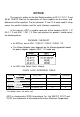
NOTICE This manual is written for the Auto Switch products of AS-41 1 P/41 1 S and AS-81 1P/811S. Most of the operations of these models are the some, and differences will be specified. The last character ‘P’ and ‘S’ of each model’s string means the parallel interface and the serial interface respectively. In this manual, ‘AS/2’ is used to represent all the models of AS-41 1 P/ AS-41 1 S and AS-81 1 P/81 1 S. When you purchase this product it should contain the following items.
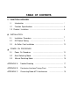
TABLE OF CONTENTS FUNCTION OVERVIEW l-l Introduction .................................................................................... 1 l-2 Function Specifications ................................................................ 4 1-3 Product Limitation .......................................................................... 6 INSTALLATION ................................................................... 7 2-l Installation Procedure 2-2 DIP Switch Setting 2-3 As Buffer Card Installation ..
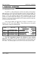
AS/2 Auto Switch FUNCTION OVERVIEW 1 FUNCTION OVERVIEW l-1 INTRODUCTION The AS/2 is a high performance and low cost printer sharing device which operates in either auto switching mode or manual switching mode. The AS/2 allows up to four or eight source devices to share one common destination devices. In the auto switching mode the AS/2 automatically locks on and services the source device that requests to link with the common device.
FUNCTION OVERVIEW AS/2 Auto Switch 1-2 FUNCTION SPECIFICATIONS PARALLEL MODEL FUNCTIONS Power Supply . .
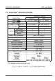
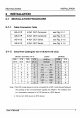
FUNCTION OVERVIEW AS/2 Auto Switch SERIAL MODEL AS-81 1 s AS-41 1 S FUNCTIONS Power Supply AC 9V, 300mA (spare) Cable Length 15M CONNECTOR INPUT (Female) 4 RS-232C (DCE) 8 RS-232C (DCE) (DB-25) OUTPUT (Male) 1 RS-232C (DTE) 1 RS-232C (DTE) 1 Input Status LED I Power 4 1 Manual 1 I 8 1 1 Input Arbitration First Come, First Serve Function Key Manual Select input Port Selection Auto or Manual Time out Selection 10-90 sec. Operation Temp.
FUNCTION OVERVIEW AS/2 Auto Switch 1-3 PRODUCT LIMITATION AS/2 is a well designed quality product. Its maximum performance and limitation is described as follows. l AS/2's Auto Switching Mode is only suitable for devices which use ‘Hardware’ Handshaking, Xon-Xoflf Handshaking is not allowed. l AS/2's Manual Switching Mode is suitable for all kinds of Handshaking Modes. l For models of AS-41 1 P and AS-81 1 P, the cable length is limited to no more than 6 meters.
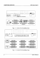
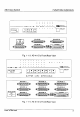
AS/2 Auto Switch INSTALLATION 2-3 AS Buffer Card Installation AS buffer card has 64K, 256K or 1M bytes of memory and is used to expand the buffer memory of AS-41 1 P and AS-81 1 P auto switches. 1) Unscrew the 4 screws on both sides of the case. 2) Lift up the upper case. 3) Find the 14 x 2 gold pin connector on the PCB for AS-41 1 P users: see Fig 2-3-l. for AS-81 1 P users: see Fig 2-3-2.
INSTALLATION AS/2 Auto Switch Fig 2-3-2 The AS-81 1 P’s Buffer Card Installation 14 User’s Manual
AS/2 Auto Switch POWER ON PROCEDURE 3 POWER ON PROCEDURE 3-1 POWER ON PROCEDURE 1) To reset the AS-81 1 P and AS-41 1 P (w/ buffer card), turn off/on power switch. AS-41 1 P (w/o buffer card) can be reset by recycling printer power while it is hooked to a printer. 2) After reset, the input channel’s service LEDs are on. Meanwhile, the AS/2 is ready for operation and it enters the auto switching mode automatically.
POWER ON PROCEDURE AS/2 Auto Switch 3) When the ‘READY’ LED turns off, it indicates Connectors are not properly connected, Printer(or output device) is not switched on, Printer is not in ON-LINE status, or, Printer is out of paper. If buffer card installed for output ‘READY’ LED reflects buffer readiness. 4) When the AS/2 is serving a certain input channel, it does not switch to serve another channel even though the printing gets interrupted by printer’s power off or printer out of paper, etc.
APPENDIX A TROUBLE SHOOTING PROBLEM LED fails to light up Failure of data transmission SOLUTIONS Check if power is turned ON or not 1. Check if the Connector of each cable is well plugged or not. 2. Check if PC is turned ON or not. 3. Check if PRINTER is turned ON or not. 4. Check if paper for PRINTER is well prepared or not. 5. Check if Print command on PC is correct or not. 6.
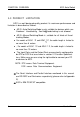
APPENDIX B CENTRONICS INTERFACE TIMING CHART Centronics Interface Timing Chart I DATA , I I I 1 I - ACK () -_____-___---______________ (min) 18 User’s Manual
APPENDIX C PREVENTING RADIO&TV INTERFERENCE Warning this equipment generates, uses and radiates radio frequency energy and if not installed and used in accordance with the instruction manual may cause interference to radio and television reception.