Master View CPU Switch CS-102/CS-122 User's Manual Packing Checklist 1 CS-102 or CS-122 CPU Switch 1 User's Manual Please read this manual thoroughly and follow the installation procedures carefully to prevent any damage to the CS-102/CS-122 and/or the devices it connects to. ©Copyright 1995 Aten® International Co., Ltd. Manual Part No. PAPE-0135-100 Printed in Taiwan 08/95 All brand names and trademarks are the registered property of their respective owners.
Introduction The CS-102 or CS-122 CPU Switch is a controller for one user to access multiple computers. Before the development of the Master View, the only way to control multiple computer configurations from a single console was through a complex and costly network system. Now, with a Master View CPU Switch, you can easily access multiple computers in a cost effective manner. The CS-102 and CS-122 are basically similiar in their functions. The difference is that the latter offers PS/2 mouse ports.
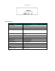
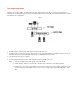
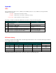
CS-122 Side View Specifications Function Specification Power Consumption DC 9V 160mA (max.) PC Connections 2 PC Selected By Keyboard/Button LEDs 1 Power 2 Ready 2 Select + * Scan Interval 3, 10, 20, 40 Sec.
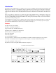
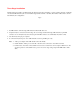
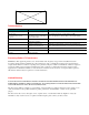
Installation Installation is fast and easy; plugging cables into their appropriate ports is all that is entailed. A Master View CS-102/CS122 unit can control two PCs. To control even more computers, units can be cascaded to three levels, with each other, and down from CS-104s and CS-106s. One Stage Installation A One Stage Installation enables one CS-102 or CS-122 to control up to two computers, as shown in Fig. A, below. Fig. A 1. Set DIP switch 4 to ON. 2.
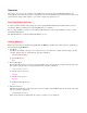
Two Stage Installation Adding a second stage enables one CPU Switch (the first stage CS-104 or CS-106) to control computers directly or indirectly via cascaded CPU Switches (the second stage CS-102, CS-104 or CS-106). The number of PCs under control is determined by the configuration. Fig. B 1. Set DIP switch 4 of the first stage CPU Switch to ON and all others off. 2. Computers may be connected to the first stage and the second stage CPU Switches.
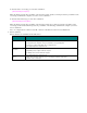
Three Stage Installation Adding a third stage enables one CPU Switch (the first stage CS-104 or CS-106) to control computers directly or indirectly via cascaded CPU Switches (the second and third stage CS-102, CS-104 or CS-106). The number of PCs under control is determined by the configuration. Fig. C 1. Set DIP switch 4 of the first stage CPU Switch to ON and all others off. 2. Computers may be connected to the first stage, the second stage, and the third stage CPU Switches.
Operation There are two ways to access any computer on the installation: by pressing the front panel SELECT BUTTON, or by entering Hot Keys from the keyboard. Once a computer has been accessed, the CPU Switch directs keyboard control, mouse control, and video image of that computer to you as if the computer were right next to you. Front Panel Button Selection To select a computer with this method, simply press the front panel SELECT BUTTON of the CPU Switch it connects to several times.
To directly select a second stage port, enter this combination: [Alt+Ctrl+Shift]+#+#+[Enter] Where the first # represents the port number on the first stage switch, and the second # represents the port number on the second stage switch that the computer you wish to access is attached to.
Appendix LEDs The CS-102/CS-122 contains one Power LED, two Ready LEDs, and two Port Select LEDs on its front panel. Their indications are as follows: Power LED: Lights when the CPU Switch is running. Ready LED: Lights when the connected PC or CPU Switch is running. Port Select LED: Lights to indicate the currently selected port.
Troubleshooting Symptom Cause Action 1st stage CS-102/CS-122 does not take Hot Keys. Incorrect DIP Switch settings. Set the First Stage CS-102/CS-122 DIP Switch 4 to ON; for all other (cascaded) CS-102 units, set DIP Switch 4 to OFF. Pressing Hot Keys gets no response. CS-102/CS-122 is in Scan Mode or Previous/Next Mode. Press the Spacebar to exit Scan Mode or Previous/Next Mode. Selected port connects to a powered off computer. Change the port selection to a powered on computer.