0DVWHU 9LHZ 3OXV &38 6ZLWFK 8VHU¶V 0DQXDO &6
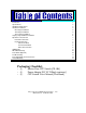
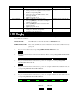
Introduction Specifications Hardware Requirements Hardware Installation One Stage Installation Two Stage Installation Three Stage Installation Step-by-Step Hardware Installation Operation of the CS-104 Front Panel Selection Keyboard Selection Auto-Scan Mode Previous/Next Mode Direct Port Selection LED Display DIP Switch Settings Foot Switch (Optional) Troubleshooting Preventing Radio & TV Interference Limited Warranty Packaging Checklist: • • • (1) (1) (1) Master View CPU Switch [CS-104] Power Adapter [D
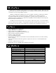
,QWURGXFWLRQ Master View is a controller for that will allow one user to access multiple computers. Before, the costly network was the only solution for this application. Now, the Master View provides the easiest and the most cost-effective way of accessing multiple computers. With the powerful features of Master View, anyone is capable of operating or testing many computers with one of each, a monitor, a keyboard and a mouse.
+DUGZDUH 5HTXLUHPHQWV You will need to have the following: To connect to a Monitor: • A VGA, SVGA, or Multisync monitor card installed in each PC. • One VGA, SVGA or Multisync Monitor To connect a Mouse: • DB-9 serial port or 6-pin mini-DIN PS/2 bus mouse port in each PC. • One PS/2 mouse and/or a DB-9 Serial Mouse To connect a Keyboard: • 5-pin DIN AT keyboard port with +5V DC on pin 5 and ground on pin 4, or a 6-pin mini-DIN PS/2 keyboard port with +5V DC on pin 4 and ground on pin 3.
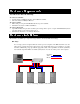
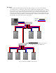
Two Stage: In a two stage system the CS-104 can either control PC’s directly or it can control other CS-104’s (second stage units) or a combination of both. In this configuration the maximum number of computers that can be in the system is 16. The DIP switch #4 on the first stage unit (The CS-104 directly connected to the monitor, mouse, and keyboard) is placed in the ON position. All other CS-104 units have DIP switch #4 in the OFF position.
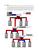
Three Stages: tion. Similar to a Two-Stage configuration, more computers can be controlled by adding another layer of CS104 units. In a three-stage system the maximum number of computers that can be controlled is increased to 64. The DIP switch #4 on the first stage unit (The CS-104 directly connected to the monitor, mouse, and keyboard) is placed in the ON position.
6WHS E\ 6WHS +DUGZDUH ,QVWDOODWLRQ Setting up one CS-104 The connection of the Keyboard, Video and the Mouse is accomplished by using the same cables that you would use to connect them to a PC. 1. • • • 2. • • 3. • 4. • • • Connecting the mouse: If you are using a PS/2 style mouse connect the 6-pin mini-DIN male plug of the PS/2 mouse to the female PS/2 port located in the CONSOLE section on the back of the CS-104.
then enter the command keystrokes and complete the command by hitting the [Enter] key.
Actions Taken by the CS-104 MODE Scan Previous/Next Direct Result for correct Hot Key • Filters out Hot Keys and beeps once • Scans powered-on computers one-by-one and flashes corresponding LED • Scan rate is set by the DIP switches of the first-stage CS-104 • [Space] stops this mode • Filters out Hot Keys and beeps once • The right [Shift] key selects the next higher numbered computer • The left [Shift] selects the next lower numbered computer • [Space] stops this mode • Filters out Hot Keys and beeps o
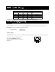
',3 6ZLWFK 6HWWLQJV The Following DIP Switch settings are for the first-stage CS-104 ONLY DIP Switch Number 1 ON OFF ON OFF 2 ON ON OFF OFF 3 X X X X Function 4 ON ON ON ON Scan Time 3 Seconds 10 Seconds 20 Seconds 40 Seconds The DIP Switch settings for the second and third-stage CS104s are all switches off. )RRW 6ZLWFK 2SWLRQDO FUNCTION The Foot Switch is an extension of the front panel Push Button, both have the same function.
7URXEOHVKRRWLQJ Symptom Possible Causes What to do The first-stage CS-104 unit will not take Hot Key commands. Incorrect DIP switch settings . Pressing the Hot Keys get no response. The CS-104 is operating in either AutoScan or Previous/ Next mode. Set the first-stage CS-104 DIP switch #4 to ON. Turn all other CS-104s’ switches OFF. Check the PORT STATUS LEDs for a flash pattern. Or Press the space bar to exit these modes before giving Hot Key Commands.
35(9(17,1* 5$',2 79 ,17(5)(5(1&( WARNING!!! This equipment generates, uses and can radiate radio frequency energy and, if not installed and used in accordance with the instruction manual, may cause interference to radio communications. This equipment has been tested and found to comply with the limits for a Class A computing device pursuant to Subpart J of Part 15 of FCC Rules, which are designed to provide reasonable protection against such interference when operated in a commercial environment.