User Manual CS-1708 CS-1716 2004-04-27
NOTE: This equipment has been tested and found to comply with the limits for a Class B digital device pursuant to Subpart J of Part 15 of the FCC Rules. These limits are designed to provide reasonable protection against harmful interference in a residential installation. This equipment generates, uses and can radiate radio frequency energy and, if not installed and used in accordance with the instructions, may cause harmful interference to radio communications.
CS-1708 / CS-1716 User Manual Packing List The complete Master View CS-1708 / CS-1716 package consists of: M 1 CS-1708 or CS-1716 KVM Switch M 2 CS Custom 2-in-1 KVM Cables (1.8m) M 1 Firmware Upgrade Cable M 1 Power Adapter M 1 Rack Mount Kit M 1 User Manual M 1 Quick Start Guide Check to make sure that all the components are present and that nothing was damaged in shipping. If you encounter a problem, contact your dealer.
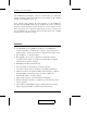
CS-1708 / CS-1716 User Manual Contents 1. Introduction Overview . . . . . . . . Features . . . . . . . . . Hardware Requirements Console . . . . . . Computer . . . . . Cables . . . . . . . . . . . . . . . . . . . . . . . . . . . . . . . . . . . . . . . . . . . . . . . . . . . . . . . . . . . . . . . . . . . . . . . . . . . . . . . . . . . . . . . . . . . . . . . . . . . . . . . . . . . . . . . . . . . . . . . . . . . . . . . . . . . . . . . . . . . . . . . . . . . . . . . . . . .
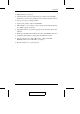
CS-1708 / CS-1716 User Manual 4. OSD Operation OSD Overview . . . . . . . OSD Navigation . . . . . . OSD Main Screen Headings OSD Functions . . . . . . . F1 GOTO: . . . . . . . F2 LIST: . . . . . . . . F3 SET: . . . . . . . . F4 ADM: . . . . . . . F5 SKP: . . . . . . . . F6 BRC: . . . . . . . . F7 SCAN: . . . . . . . F8 LOUT: . . . . . . . . . . . . . . . . . . . . . . . . . . . . . . . . . . . . . . . . . . . . . . . . . . . . . . . . . . . . . . . . . . . . . . . . . . . . . . . . . . . . . . . .
CS-1708 / CS-1716 User Manual Conventions This manual uses the following conventions: Courier Indicates text that you should key in. [] Indicates keys you should press. For example, [Enter] means to press the Enter key. If keys need to be chorded, they appear together in the same bracket with a plus sign between them: [Ctrl+Alt]. 1. Numbered lists represent procedures with sequential steps. M Bullet lists provide information, but do not involve sequential steps.
Chapter 1. Introduction Overview The Master View CS-1708 and CS-1716 KVM Switches are control units that allow access to multiple computers from a single console (keyboard, mouse, and monitor). A single Master View can control up to eight (CS-1708) or 16 (CS-1716) computers. As many as 31 additional switches can be added in a daisy chain configuration, allowing up to 512 computers to be controlled from a single keyboard-monitor-mouse console.
CS-1708 / CS-1716 User Manual driven OSD (On Screen Display) system. A convenient Auto Scan feature also permits automatic scanning and monitoring of the activities of all computers running on the installation one by one.
Introduction w Multimedia keyboard support w Administrator/User password authorization for enhanced security (PSP); administrator synchronized confirmation between master and slave stations w Two types of logout - manual and timed w Superior video quality - 2048 x 1536; DDC2B w DDC emulation - video settings of each computer is automatically adjusted for optimum output to the monitor w Upgradable firmware - all switches upgraded at the same time via the daisy chain bus w Backward compatible with the Mas
CS-1708 / CS-1716 User Manual Hardware Requirements Console w A VGA, SVGA, or Multisync monitor capable of the highest resolution that you will be using on any computer in the installation. w A USB mouse w A USB keyboard Computer The following equipment must be installed on each computer: w A VGA, SVGA or Multisync card. w Type A USB port. Cables Substandard cables may damage the connected devices or degrade overall performance.
Chapter 2. Installation CS-1708 / CS-1716 Front View 1 2 3 4 2 3 4 1 5.
CS-1708 / CS-1716 User Manual 1. Port LEDs: The Port LEDs provide status information about their corresponding CPU Ports. There is one pair of LEDs for each Port. The one on the left is the On Line LED; the one on the right is the Selected Port LED: w An On Line LED lights ORANGE to indicate that the computer attached to its corresponding port is up and running. w A Selected LED lights GREEN to indicate that the computer attached to its corresponding port is the one that has the KVM focus.
Installation CS-1708 / CS-1716 Rear View 1 3 4 2 7 5 6 1 3 4 5 6 2 7 7.
CS-1708 / CS-1716 User Manual 1. Daisy Chain Ports: When Daisy Chaining Units, the cables plug in here. The port on the left is the Chain In port; the one on the right is the Chain Out port. 2. CPU Port Section: The cables that link to the computers plug in here. The shape of these connectors has been specifically modified so that only cables designed to work with this switch can plug in. 3.
Installation Installation Before you Begin 1. Make sure that power to all the devices you will be connecting up have been turned off. You must unplug the power cords of any computers that have the Keyboard Power On function. Otherwise, the switch will receive power from the computer. 2. To prevent damage to your installation make sure that all devices on the installation are properly grounded. Single Stage Installation Refer to the installation diagrams on the next page as you perform the following steps.
CS-1708 / CS-1716 User Manual 2 3 1 2 2 10.
Installation Daisy Chaining To control even more computers, up to 31 additional switches can be daisy chained down from the first unit. As many as 512 computers can be controlled from a single console in a complete installation. Tables showing the relation between the number of computers and the number of Master View CS-1708 / CS-1716 units needed to control them are provided on p. 45 in the Appendix. To set up a daisy chained installation, do the following: 1.
CS-1708 / CS-1716 User Manual 12.
Installation Hot Plugging The CS-1708 / CS-1716 supports hot plugging - components can be removed and added back into the installation by unplugging their cables from the ports without the need to shut the unit down. In order for hot plugging to work properly, however, the procedures described below must be followed: Switching Station Positions: You can switch station positions by simply unplugging from the old parent and plugging into a new one.
CS-1708 / CS-1716 User Manual Port ID Numbering Each CPU port on a Master View installation is assigned a unique Port ID. The Port ID is made up of two parts: a two-digit Station Number, and a two-digit Port Number: w The Station Number - reflects the switch’s position in the daisy chain sequence. This corresponds to the number displayed on the front panel Station ID LED. w The Port Number - reflects the port on the Station that the computer is connected to.
Chapter 3. Hotkey Operation The CS-1708 / CS-1716 ’s hotkey function makes it convenient to control your KVM installation from the keyboard. Note: The hotkey function must be enabled to use hotkey operations. See Hotkey Command Mode, p. 28 for details. Invoking Hotkey Mode (HKM) All hotkey operations begin by invoking HKM. To invoke HKM, do the following: 1. Press and hold down the Num Lock key 2. Press and release the Minus key 3. Release the Num Lock key [Num Lock] + [-] Note: 1.
CS-1708 / CS-1716 User Manual Hotkey Port Access Hotkey Port Access allows you to select which computer has the KVM focus. The CS-1708 / CS-1716 provides the following Hotkey Port Access features: w Selecting the Active Port w Auto Scan Mode Selecting the Active Port: You can bring the KVM focus to any computer with a hotkey combination that specifies its Port ID (see p. 14 for Port ID Numbering details): 1. Invoke HKM (see p. 15). 2. Key in the computer’s Port ID number.
Hotkey Operation Auto Scan Mode: The CS-1708 / CS-1716’s Auto Scan feature automatically switches among all the active CPU Ports that are accessible to the currently logged on User at regular intervals (see Scan Mode of the OSD F3 SET function, p. 28), so that he can monitor their activity automatically. To start Auto Scanning, key in the following Hotkey combination: 1. Invoke Hotkey Mode (see p. 15) 2. Key in [A] After you press A, you automatically exit Hotkey Mode, and enter Auto Scan Mode. 3.
CS-1708 / CS-1716 User Manual Hotkey Configuration Alternate Hotkey Invocation Keys: An alternate set of Hotkey Invocation keys is provided in case the default set conflicts with programs running on the computers. To switch to the alternate Hotkey Invocation set, do the following: 1. Invoke HKM (see p. 15) 2. Press and release the H key The Hotkey Invocation keys become the Ctrl key (instead of Num Lock) and the F12 key (instead of Minus). Note: This procedure is a toggle between the two methods.
Hotkey Operation Platform Setup: The CS-1708 / CS-1716’s default port settings are for a PC Compatible operating platform. You can modify the platform setting for each port by bringing the KVM focus to the port you want to change and using the hotkey combinations shown in the table below. Key Operation [F1] Sets the PC Compatible keyboard operating platform for the port that currently has the KVM focus. [F2] Sets the Mac keyboard operating platform for the port that currently has the KVM focus.
CS-1708 / CS-1716 User Manual Miscellaneous Actions: Hotkeys are also used to reset the USB, and toggle the beeper On and Off. To perform any of these operations, do the following: 1. Invoke HKM (see p. 15) 2. Press and release the appropriate action key (see table). Key Operation [F5] Performs a USB reset B Toggles the Beeper On or Off. The Command Line displays Beeper On or Beeper Off for one second; then the message disappears and you automatically exit HKM.
Hotkey Operation Keyboard Emulation Sun Keyboard: The PC Compatible (101/104 key) keyboard can emulate the functions of the Sun keyboard when the Control key [Ctrl] is used in conjunction with other keys. The corresponding functions are shown in the table below. Note: When using [Ctrl] combinations, press and release the Ctrl key, then press and release the activation key.
CS-1708 / CS-1716 User Manual Mac Keyboard: The PC Compatible (101/104 key) keyboard can emulate the functions of the Mac keyboard. The emulation mappings are listed in the table below. Note: When using key combinations, press and release the first key (Ctrl or Alt), then press and release the activation key.
Chapter 4. OSD Operation OSD Overview The On Screen Display (OSD) is used to handle all computer control and switching procedures. All procedures start from the OSD Main Screen. To pop up the Main Screen, tap the [Scroll Lock] key twice. Note: You can change the Hotkey to the Ctrl key (see OSD Hotkey, p. 27). The OSD incorporates a two level (Administrator / User) authorization system. Before the OSD Main Screen comes up, a dialog box appears that asks you to provide your Username and Password.
CS-1708 / CS-1716 User Manual Please note the following: w The diagram depicts the Administrator’s Main Screen. The User Main Screen does not show the F4 ADM function. w OSD always starts in List view, with the highlight bar at the same position it was in the last time it was closed. w Only the ports that have been set accessible by the Administrator for the currently logged in User are visible (see Set Accessible Ports, p. 31, for details).
OSD Operation OSD Main Screen Headings Heading Explanation SN-PN This column lists the Port ID numbers (see Port ID Numbering, p. 14), for all the CPU ports on the installation. The simplest method to access a particular computer is move the Highlight Bar to it, then press [Enter]. QV If a port has selected for Quick View scanning (see Set Quick View Ports, p. 31), an arrowhead symbol displays in this column to indicate so.
CS-1708 / CS-1716 User Manual F1 GOTO: GOTO allows you to switch directly to a port either by keying in the port’s Name, or its Port ID. w To use the Name method, key in 1; key in the port’s Name; then press [Enter]. w To use the Port ID method, key in 2; key in the Port ID; then press [Enter]. Note: You can key in a partial Name or Port ID. In that case, the screen will show all the computers that the User has View rights to (see Set Accessible Ports, p.
OSD Operation Move the Highlight Bar to the choice you want, then press [Enter]. An icon appears before the choice to indicate that it is the currently selected one. After you make your choice and press [Enter], you return to the OSD Main Screen with the newly formulated List displayed. F3 SET: This function allows the Administrator and each User to set up their own working environment.
CS-1708 / CS-1716 User Manual (F3 SET: continued) Setting Function PORT ID DISPLAY MODE Selects how the Port ID is displayed: the Port Number alone (PORT NUMBER); the Port Name alone (PORT NAME); or the Port Number plus the Port Name (PORT NUMBER + PORT NAME). The default is PORT NUMBER + PORT NAME. SCAN DURATION Determines how long the focus dwells on each port as it cycles through the selected ports in Auto Scan Mode (see p. 35). Key in a value from 1 - 255 seconds, then press [Enter].
OSD Operation F4 ADM: F4 is an Administrator only function. It allows the Administrator to configure and control the overall operation of the OSD. To change a setting Double Click it; or use the Up and Down Arrow Keys to move the highlight bar to it then press [Enter]. After you select an item, a submenu with further choices for you to select from appears. Double Click the choice you want, or move the Highlight Bar to it then press [Enter].
CS-1708 / CS-1716 User Manual (F4 ADM: continued) Setting EDIT PORT NAMES Function To help remember which computer is attached to a particular port, every port can be given a name. This function allows the Administrator to create, modify, or delete port names. Note: Only the Ports currently chosen for the LIST view on the main OSD screen (see p. 26), show up here. To Edit a port name: 1. Use the Navigation Keys to move the highlight bar to it, then press [Enter]. 2.
OSD Operation (F4 ADM: continued) Setting SET QUICK VIEW PORTS Function This function lets the Administrator select which Ports to include as Quick View ports. Note: Only the Ports currently chosen for the LIST view on the main OSD screen (see p. 26), show up here. w To select/deselect a port as a Quick View Port, use the Navigation Keys to move the highlight bar to it, then Press [Space].
CS-1708 / CS-1716 User Manual (F4 ADM: continued) Setting RESET STATION IDS Function If you change the position of one of the Stations in the daisy chain, the OSD settings will no longer correspond to the new situation. This function directs the OSD to rescan the Station positions of the entire installation and updates the OSD so that the OSD Station information corresponds to the new physical layout. Note: Only the Station Numbers get updated.
OSD Operation F5 SKP: Skip (SKP) Mode enables you to easily skip backward or forward - switching the console focus from the currently active computer port to the previous or next available one. w The selection of computers to be available for Skip Mode switching is made with the Scan/Skip Mode setting under the F3 SET function (see p. 28).
CS-1708 / CS-1716 User Manual F6 BRC: F6 is an Administrator only function. When this function is in effect, commands sent from the keyboard are broadcast to all available computers on the installation. This function is particularly useful for operations that need to be performed on multiple computers, such as performing a system wide shutdown, installing or upgrading software, etc. BRC works in conjunction with the F2 LIST function. The LIST function (see p.
OSD Operation F7 SCAN: The SCAN function allows you to automatically switch among the available computers at regular intervals so that you can monitor their activity without having to take the trouble of switching manually. w The selection of computers to be included for Auto Scanning is made with the Scan Mode setting under the F3 SET function (see p. 28). w The amount of time that each Port displays for is set with the Scan Duration setting under the F3 SET function (see p. 28).
CS-1708 / CS-1716 User Manual F8 LOUT: LOUT (Log out) logs you out of OSD control of the computers, and blanks the Console screen. After using this function you must log in all over again to regain access to the OSD. This is different from simply pressing [Esc] when you are at the Main Screen to deactivate the OSD, where all you have to do to reenter the OSD is tap the OSD Hotkey. Note: 1. When you reenter the OSD after logging out, the screen stays blank except for the OSD Main Menu.
Chapter 5. The Firmware Upgrade Utility The Windows-based Firmware Upgrade Utility (FWUpgrade.exe) provides a smooth, automated process for upgrading the KVM switch’s firmware. The Utility comes as part of a Firmware Upgrade Package that is specific for each device. New firmware upgrade packages are posted on our web site as new firmware revisions become available. Check the web site regularly to find the latest packages and information relating to them: http://www.aten.com.
CS-1708 / CS-1716 User Manual 4. Shut down the computers on your CS-1708 / CS-1716 installation. 5. From your KVM switch console, bring up the OSD (see p. 23) and select the F4ADM function. 6. Scroll down to FIRMWARE UPGRADE (see p. 32). Press [Enter], then press [Y] to invoke Firmware Upgrade Mode For your reference, the current firmware upgrade version displays on the screen. Starting the Upgrade To upgrade your firmware: 1.
The Firmware Upgrade Utility 3. Click Next to continue. The Firmware Upgrade Utility main screen appears: The Utility inspects your installation. All the devices capable of being upgraded by the package are listed in the Device List panel. 4. As you select a device in the list, its description appears in the Device Description panel. 39.
CS-1708 / CS-1716 User Manual 5. After you have made your device selection(s), Click Next to perform the upgrade. If you enabled Check Firmware Version, the Utility compares the device’s firmware level with that of the upgrade files. If it finds that the device’s version is higher than the upgrade version, it brings up a dialog box informing you of the situation and gives you the option to Continue or Cancel.
The Firmware Upgrade Utility Upgrade Succeeded After the upgrade has completed, a screen appears to inform you that the procedure was successful: Click Finish to close the Firmware Upgrade Utility. 41.
CS-1708 / CS-1716 User Manual Upgrade Failed If the upgrade failed to complete successfully a dialog box appears asking if you want to retry. Click Yes to retry. If you Click No, the Upgrade Failed screen appears: Click Cancel to close the Firmware Upgrade Utility. See the next section, Firmware Upgrade Recovery, for how to proceed. 42.
The Firmware Upgrade Utility Firmware Upgrade Recovery There are basically three conditions that call for firmware upgrade recovery: w When you begin a firmware upgrade, but decide not to proceed with it. w When the Mainboard firmware upgrade fails. w When the I/O firmware upgrade fails. Note: If one of the cascaded switches fails to upgrade successfully, unplug it from the installation and perform the recovery and upgrade operation independently.
CS-1708 / CS-1716 User Manual Notes: 44.
Appendix Master View Connection Tables The following tables indicate the relationship between the number of Master View Units and the number of computers that they control: CS-1716: MVs Computers MVs Computers MVs Computers MVs Computers 1 1 - 16 9 129 - 144 17 257 - 272 25 385 - 400 2 17 - 32 10 145 - 160 18 273 - 288 26 401 - 416 3 33 - 48 11 161 - 176 19 289 - 304 27 417 - 432 4 49 - 64 12 177 - 192 20 305 - 320 28 433 - 448 5 65 - 80 13 193 - 208 21 321 - 33
CS-1708 / CS-1716 User Manual Clear Login Information If you are unable to perform an Administrator login (because the Username and Password information has become corrupted, or you have forgotten it, for example), you can clear the login information with the following procedure: 1. Power off the switch and remove its housing. 2. Short the jumper labeled Default Password at the right front of the switch’s main board. 3. Power on the switch.
The Firmware Upgrade Utility Rack Mounting The CS-1708 / CS-1716 can be mounted in a 1U system rack. For convenience and flexibility, the mounting brackets can screw into either the front or the back of the unit so that it can attach to the front or the back of the rack. To rack mount the unit do the following: 1. Screw the mounting brackets into the sides of the unit at the front or the rear, as shown in the diagram below. 2. Slide the unit into the rack and secure it to the rack. 47.
CS-1708 / CS-1716 User Manual Specifications Function CS-1708 CS-1716 Computer Connections 8 CPU Port Selection Hotkeys; OSD LEDs On Line 8 (Orange) 16 (Orange) Selected 8 (Green) 16 (Green) Power 1 (Blue) Station ID 2 x 7 Segments Keyboard 1 x USB Type A Mouse 1 x USB Type A Video 1 x HDB -15 female Console Connectors 16 CPU Connectors 8 x SPDB - 15 female 16 x SPDB - 15 female Daisy Chain Ports 1 x DB-25 male: 1 x DB-25 female Firmware Upgrade 1 x RJ-11 socket Power Consu
The Firmware Upgrade Utility OSD Factory Default Settings The factory default settings are as follows: Setting Default OSD Hotkey [Scroll Lock] [Scroll Lock] Port ID Display Position Upper Right Corner Port ID Display Duration 3 Seconds Port ID Display Mode The Port Number plus the Port Name Scan Duration 5 Seconds Scan/Skip Mode All Screen Blanker 0 (Disabled) Logout Timeout 0 (Disabled) Beeper Y (Activated) Accessible Ports F (Full) For all Users on all Ports Operating System PC K
CS-1708 / CS-1716 User Manual Troubleshooting Symptom Possible Cause Action After installation, my Sun/Mac computer does not boot. Operating System not properly set for its port. When you install a Sun or Mac computer, before you run it for the first time you must set the correct operating system for the port it is connected to, otherwise, it will not boot. See SET OPERATING SYSTEM, p. 32, for details. Keyboard and/or Mouse not responding. Keyboard and/or mouse need to be reset.