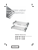
User Manual CS-9134 CS-9138 2005-12-21
This equipment has been tested and found to comply with the limits for a Class A digital device, pursuant to Part 15 of the FCC Rules. These limits are designed to provide reasonable protection against harmful interference when the equipment is operated in a commercial environment. This equipment generates, uses and can radiate radio frequency energy and, if not installed and used in accordance with the instruction manual, may cause harmful interference to radio communications.
Packing List The complete Master View CS-9134 / CS-9138 package consists of: w 1 CS-9134 or CS-9138 KVM Switch w 1 Power Adapter w 1 Rack Mounting Kit w 1 User Manual w 1 Quick Start Guide Check to make sure that the unit was not damaged in shipping. If you encounter a problem, contact your dealer. Read this manual thoroughly and follow the installation and operation procedures carefully to prevent any damage to the unit, and/or any of the devices connected to it.
Contents Packing List . . . . . . . . . . . . . . . . . . . . . . . . . . . . . . . . . iii Contents . . . . . . . . . . . . . . . . . . . . . . . . . . . . . . . . . . . iv Overview . . . . . . . . . . . . . . . . . . . . . . . . . . . . . . . . . . . 1 Features . . . . . . . . . . . . . . . . . . . . . . . . . . . . . . . . . . . 2 Hardware Requirements. . . . . . . . . . . . . . . . . . . . . . . . . . . 3 Console . . . . . . . . . . . . . . . . . . . . . . . . . . . . . . . . . . 3 Computers. . . . . .
Overview The Master View CS-9134 and CS-9138 KVM switches are control units that allow access to multiple computers from a single console (keyboard, monitor, and mouse). Before the development of the Master View, the only way to control multiple computer configurations from a single console was through a complex and costly network system. Now, with the Master View CS-9134 / CS-9138, you can easily access multiple computers in a cost effective manner.
Features w Cascadable To Three Levels - Control Up to 64 (CS-9134) or 512 (CS-9138) Computers From a Single Console w No Software Required - Computer Selection via Front Panel Switches, Hot Keys, or OSD (On Screen Display) w Quick View Scan Feature for Monitoring Selected Computers w PS/2 and Serial Mouse Emulation For System Bootup w Console’s PS/2 Mouse Controls All Connected Computers - Even Those With Serial Mice w PS/2 Compatible Mouse Support - Microsoft Intellimouse Explorer and Logitech FirstMou
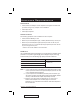
Hardware Requirements Console w A VGA, SVGA, or Multisync monitor capable of the highest resolution that you will be using on any computer in the installation. w A PS/2 style mouse w A PS/2 style keyboard Computers The following equipment must be installed on each computer: w A VGA, SVGA or Multisync card. w Either a 6-pin mini-DIN (PS/2 style), or DB-9 (standard serial), mouse port.
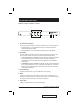
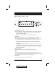
Introduction CS-9134 Front View 1 K/M RESET AUTO SCAN 2 3 4 5 1. Port Selection Switches Press a switch to access the computer attached to the corresponding port. w Pressing Buttons 1 and 2 simultaneously for 3 seconds performs a Keyboard and Mouse Reset. w Pressing Buttons 3 and 4 simultaneously starts Auto Scan Mode. 2. Port LEDs The Port LEDs are built into the Port Selection Switches.
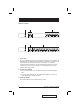
CS-9138 Front View 1 K/M RESET AUTO SCAN 2 3 4 5 1. Port Selection Switches Press a switch to access the computer attached to the corresponding port. w Pressing Buttons 1 and 2 simultaneously for 3 seconds performs a Keyboard and Mouse Reset. w Pressing 7 and 8 simultaneously starts Auto Scan Mode. 2. Port LEDs The Port LEDs are built into the Port Selection Switches.
Rear View 1 2 1 2 3 3 1. Power Jack The unit is designed to be non-powered (external power is not required - its operating power comes from the computers). In general, the only time that external power is necessary is when you cascade it, or if operation becomes erratic because the unit isn’t obtaining enough power from the computer connections. If you choose to use external power, the power adapter cable plugs in here. 2.
Installation Before you Begin 1. Make sure that the power to each of the devices you will be connecting up has been turned off. You must unplug the power cords of any computers that have the Keyboard Power On function. 2. Make sure that all devices on the installation are properly grounded. Single Station Installation In a Single Stage installation, there are no additional Master View’s cascaded down from the first unit. To set up a single stage installation do the following: 1.
Two Stage Installation To control even more computers, up to four (CS-9134) or eight (CS-9138) additional Master View units can be cascaded from the CPU ports of the First Stage unit. The cascaded Master Views that connect back to the First Stage unit are considered Second Stage units. As many as 16 (CS-9134) or 64 (CS-9138) computers can be controlled in a complete two stage installation.
Three Stage Installation The procedures for setting up a three stage installation are essentially the same as for a two stage installation. With a three stage setup, as many as 64 (CS-9134) or 512 (CS-9138) computers can be controlled in a complete installation. A table showing the relation between the number of computers and the number of Master View units needed to control them is provided in the Appendix. Note: Master View units cannot be cascaded beyond the third level.
4. Plug the power adapter cable into the Master View’s Power Jack, then plug the adapter into an AC power source. 5. Repeat these steps for any other Third Stage units you wish to connect. 6. Plug in the power adapters for all the Second Stage Master View units. 7. Plug in the power adapter for the First Stage Master View unit. 8. Turn on the power to all the computers. Note: The Power On sequence requires that all Third Stage units be powered on first.
Operation Hot Plugging The Master View CS-9134 / CS-9138 supports hot plugging. Components can be removed and added back into the installation by unplugging and replugging their cables from their respective ports without the need to shut the switch down. For hot plugging to work properly, the following procedures must be observed: u Hot Plugging CPU Ports: When hot plugging cables from the CPU ports: 1. The cable must be plugged back into the same port it was removed from. 2.
Powering Off and Restarting If it becomes necessary to Power Off one of the Master View units, before starting it back up you must do the following: 1. Shut down all the computers that are attached to the unit. If there are Master View stations cascaded down from it, all the cascaded stations and the computers attached to them must be shut down, as well. Note: 1. You must unplug the power cords of any computers that have the Keyboard Power On function that are connected to the shut down switches.
Port Selection The Master View CS-9134 / CS-9138 provides three methods to obtain instant access to any computer in your installation: Manual, Hotkey, and OSD. u Manual Simply press the appropriate Port Selection Switch on the Master View’s front panel. After you press the switch, the Selected LED lights to indicate that the port has the KVM focus. The OSD (see p. 16) automatically switches to highlight the computer that you have selected. Note: 1.
Port ID Numbering Each CPU Port on a Master View installation is assigned a unique Port ID. You can directly access any computer on any level of the installation by specifying the Port ID of the CPU port that the computer is connected to either with the Hotkey port selection method, or with the OSD. The Port ID is a one, two, or three digit number. It is determined by the Stage Level and CPU Port number of the Master View unit that a computer is connected to.
Port Key In Examples 1. To access a computer attached to port 3 of a Single Stage installation, key in 3 for the Port ID, as follows: [Ctrl]+[Shift]+[Alt] 3 [Enter] 2. To access a computer attached to port 3 of a Second Stage unit that is cascaded down from port 2 of the First Stage unit, key in 2 3 for the Port ID, as follows: [Ctrl]+[Shift]+[Alt] 2 3 [Enter] Note: You must key in the numbers one at a time. 3.
OSD OSD Overview The On Screen Display (OSD) provides a menu driven interface to handle all computer control and switching procedures. Although Hotkey switching still works, using OSD is a great deal more convenient - especially in large, cascaded installations where it is difficult to keep track of which port a particular computer is attached to. All operations start from the OSD Main Menu. To pop up the Main Menu, tap either Ctrl key twice. Note: 1.
OSD Navigation w [Esc] cancels the current selection, or dismisses the current menu and moves back to the menu one level above. If you are at the highest menu level, it deactivates OSD. w To move up or down through the list one line at a time, Click the Up and Down Triangle symbols (st), or use the Up and Down Arrow Keys. If there are more items than appear on the screen, the screen will scroll.
OSD Main Screen Headings Heading Explanation PN This column lists the Port ID numbers (Station Number - Port Number), for all the CPU ports on the installation. The simplest method to access a particular computer is move the Highlight Bar to it, then press [Enter]. QV If a port has selected for Quick View scanning (see F2 and F4, below), an arrowhead symbol displays in this column to indicate so.
u F2 SCAN: Pressing [F2] initiates Quick View Scanning, in which the OSD cycles through all the ports that are currently selected for this with the QV feature (see F4 QV, below). It stays on each port for the amount of time set with the Scan Duration setting under the F6 SET function (see p. 22). When you want to stop at a particular location, press the [Spacebar] to stop scanning. When you want to stop at a particular location, press the [Spacebar] to stop scanning. Note: 1.
u F3 LIST: This function lets you broaden or narrow the scope of which ports the OSD lists. On the submenu that appears, an icon of a pointing finger indicates the currently selected choice. To change a setting, move the highlight bar to the choice you want, then press [Enter]. An explanation of the settings is given in the table below: Choice Meaning ALL Lists the Port ID numbers and Names (if names have been specified see F5, below), of all the ports on the installation.
u F4 QV: QV lets you select which ports you want to include for automatic scanning under the Quick View Scanning function (see F2, above). [F4] is a toggle. To select/deselect a port, move the highlight bar to it, then press [F4]. When a port has been selected, an arrowhead displays in the QV column to indicate so. When a port is deselected, the arrowhead disappears. u F5 EDIT: To help remember which computer is attached to a particular port, every port can be given a name.
u F6 SET: Pressing [F6] brings up the OSD configuration menu. To change a setting: 1. Move the highlight bar to the choice you want (an icon of a pointing finger indicates which choice is the currently selected one), then press [Enter]. 2. On the submenu that appears, move the highlight bar to the choice you want and press [Enter].
Setting Function SET PASSWORD Allows you to set a password in order to control access to: Clearing the Name List; Restoring Default Values; and Locking/Unlocking the Console. See the OSD Security Features section, below, for password setting details. CLEAR THE NAME LIST* Clears all Port Names from the Name List. You are asked to confirm before the procedure goes on. Key in Y, then press [Enter] to confirm. While the names are being cleared, a message appears on the display to indicate so.
OSD Factory Default Settings The factory default settings are as follows: Setting Default Display Duration Always On Display Mode The Port Number plus the Port Name Scan Duration 3 Seconds OSD Security In order to prevent unauthorized access to the systems, the OSD provides a password security feature. If a password has been set, the OSD will request that the user specify it before allowing entry. To set a password: 1. Press [F6] to bring up the setup configuration menu. 2.
Appendix Computer Connection Tables The following tables indicate the relationship between the number of Master View Units and the number of systems that they control: u CS-9138: MVs Computers MVs Computers MVs Computers MVs Computers 1 8 20 134 - 141 39 267 - 274 58 400 - 407 2 8-15 21 141 - 148 40 274 - 281 59 407 - 414 3 15 - 22 22 148 - 155 41 281 - 288 60 414 - 421 4 22 - 29 23 155 - 162 42 288 - 295 61 421 - 428 5 29 - 36 24 162 - 169 43 295 - 302 62 42
u CS-9134: MVs Computers MVs Computers MVs Computers MVs Computers 1 4 7 19 - 22 13 37 - 40 19 55 - 58 2 4-7 8 22 - 25 14 40 - 43 20 58 - 61 3 7 - 10 9 25 - 28 15 43 - 46 21 61 - 64 4 10 - 13 10 28 - 31 16 46 - 49 5 13 - 16 11 31 - 34 17 49 - 52 6 16 - 19 12 34 - 37 18 52 - 55 Troubleshooting Symptom Possible Cause Action Erratic behavior.
Stacking and Rack Mounting u Stacking CS-9134 / CS-9138 switches can be stacked one on top of the other using the stacking brackets that come already attached to the unit. Line up the four bottom brackets of the top unit with the four top brackets of the bottom unit; then fit the top unit down onto the bottom unit.
u Rack Mounting To rack mount the unit do the following: 1. First remove the stacking brackets by unscrewing them from the unit, as shown in the diagram below: 2. Next screw the mounting brackets into the sides of the unit, as shown in the diagram below: Phillips hex head M3 x 8 3. Slide the unit into the rack and secure it to the rack.
Specifications Function Computer Connections Console Connectors CPU Connectors CS-9138 Direct 4 8 Max 64 (via Cascade) 512 (via Cascade) Port Selection LEDs CS-9134 Front Panel Switches; Hotkeys; OSD Power 1 (Blue) On Line 4 (Green) 8 (Green) Selected 4 (Orange) 8 (Orange) Keyboard 1 x 6 pin mini DIN female Mouse 1 x 6 pin mini DIN female Video 1 x HDB -15 female Keyboard 4 x 6 pin mini DIN female 8 x 6 pin mini DIN female Mouse 4 x 6 pin mini DIN female 8 x 6 pin mini DIN fe
Limited Warranty IN NO EVENT SHALL THE DIRECT VENDOR’S LIABILITY EXCEED THE PRICE PAID FOR THE PRODUCT FROM THE DIRECT, INDIRECT, SPECIAL, INCIDENTAL OR CONSEQUENTIAL DAMAGES RESULTING FROM THE USE OF THE PRODUCT, DISK OR ITS DOCUMENTATION. The direct vendor makes no warranty or representation, expressed, implied, or statutory with respect to the contents or use of this documentation, and specially disclaims its quality, performance, merchantability, or fitness for any particular purpose.