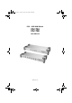
cs1754-1758.book Page i Friday, July 20, 2007 10:06 AM PS/2 – USB KVM Switch CS-1754 CS-1758 User Manual www.aten.
cs1754-1758.book Page ii Friday, July 20, 2007 10:06 AM CS-1754 / CS-1758 User Manual FCC Information This is an FCC Class A product. In a domestic environment this product may cause radio interference in which case the user may be required to take adequate measures. This equipment has been tested and found to comply with the limits for a Class A digital device, pursuant to Part 15 of the FCC Rules.
cs1754-1758.book Page iii Friday, July 20, 2007 10:06 AM CS-1754 / CS-1758 User Manual User Information Online Registration Be sure to register your product at our online support center: International – http://support.aten.com North America – http://www.aten-usa.
cs1754-1758.book Page iv Friday, July 20, 2007 10:06 AM CS-1754 / CS-1758 User Manual Package Contents 1 CS-1754 or CS-1758 KVM Switch 1 Firmware Upgrade Cable 1 Power Adapter 1 Rack Mount Kit 1 User Manual 1 Quick Start Guide Check to make sure that all the components are present and that nothing got damaged in shipping. If you encounter a problem, contact your dealer.
cs1754-1758.book Page v Friday, July 20, 2007 10:06 AM CS-1754 / CS-1758 User Manual Contents FCC Information . . . . . . . . . . . . . . . . . . . . . . . . . . . . . . . . . . . . . . . . . . . . . ii RoHS. . . . . . . . . . . . . . . . . . . . . . . . . . . . . . . . . . . . . . . . . . . . . . . . . . . . . . ii SJ/T 11364-2006. . . . . . . . . . . . . . . . . . . . . . . . . . . . . . . . . . . . . . . . . . . . . ii User Information . . . . . . . . . . . . . . . . . . . . . . . . . . . . . . . . . .
cs1754-1758.book Page vi Friday, July 20, 2007 10:06 AM CS-1754 / CS-1758 User Manual 4. OSD Operation OSD Overview . . . . . . . . . . . . . . . . . . . . . . . . . . . . . . . . . . . . . . . . . . . . . 23 OSD Navigation . . . . . . . . . . . . . . . . . . . . . . . . . . . . . . . . . . . . . . . . . . . . 24 OSD Main Screen Headings. . . . . . . . . . . . . . . . . . . . . . . . . . . . . . . . . . . 25 OSD Functions . . . . . . . . . . . . . . . . . . . . . . . . . . . . . . . . . . . . . . . . . .
cs1754-1758.book Page vii Friday, July 20, 2007 10:06 AM CS-1754 / CS-1758 User Manual About this Manual This User Manual is provided to help you get the most from your c/c system. It covers all aspects of installation, configuration and operation. An overview of the information found in the manual is provided below. Chapter 1, Introduction, introduces you to the CS-1754 / CS-1758 system. Its purpose, features and benefits are presented, and its front and back panel components are described.
cs1754-1758.book Page viii Friday, July 20, 2007 10:06 AM CS-1754 / CS-1758 User Manual Conventions This manual uses the following conventions: Monospaced [] Indicates text that you should key in. Indicates keys you should press. For example, [Enter] means to press the Enter key. If keys need to be chorded, they appear together in the same bracket with a plus sign between them: [Ctrl+Alt]. 1. Numbered lists represent procedures with sequential steps.
cs1754-1758.book Page 1 Friday, July 20, 2007 10:06 AM Chapter 1 Introduction Overview The CS-1754 and CS-1758 USB KVM (Keyboard, Video, Mouse) Switches are control units that allow access and control of up to 4 (CS-1754) or 8 (CS1758) computers from a single USB keyboard, USB mouse, and monitor console. They can be cascaded to three levels – allowing up to 21 CS-1754s to control up to 64 computers, and up to 73 CS-1758s to control up to 512 computers - all from the original single console.
cs1754-1758.
cs1754-1758.book Page 3 Friday, July 20, 2007 10:06 AM 1. Introduction Hardware Requirements Console A VGA, SVGA, or Multisync monitor capable of the highest resolution that you will be using on any computer in the installation. A USB mouse A USB keyboard Computers The following equipment must be installed on each computer: A VGA, SVGA or Multisync card. Either a Type A USB port, or PS/2 keyboard and mouse ports (see the Cables discussion, below).
cs1754-1758.
cs1754-1758.book Page 5 Friday, July 20, 2007 10:06 AM 1. Introduction No. 1 Component Port Selection Switches Description Press a switch to access the computer attached to its corresponding port. Pressing buttons 1 and 2 simultaneously for 2 seconds performs a keyboard and mouse reset. For the CS-1754, pressing buttons 3 and 4 simultaneously for 2 seconds starts Auto Scan Mode; for the CS-1758, pressing buttons 7 and 8 simultaneously for 2 seconds starts Auto Scan Mode.
cs1754-1758.
cs1754-1758.book Page 7 Friday, July 20, 2007 10:06 AM 1. Introduction No. 1 Component Description Firmware Upgrade Port The Firmware Upgrade Cable that transfers the firmware upgrade data from the administrator's computer to the switch (see page 43), plugs into this RJ-11 connector. Firmware Upgrade Reset Switch During normal operation and while performing a fimware upgrade, this switch should be in the NORMAL position.
cs1754-1758.
cs1754-1758.book Page 9 Friday, July 20, 2007 10:06 AM Chapter 2 Installation 1. Important safety information regarding the placement of this device is provided on page 49. Please review it before proceeding. 2. Make sure that power to all the devices you will be connecting up have been turned off. You must unplug the power cords of any computers that have the Keyboard Power On function.
cs1754-1758.book Page 10 Friday, July 20, 2007 10:06 AM CS-1754 / CS-1758 User Manual Rack Mounting The CS-1754 / CS-1758 can be mounted in a 1U system rack. To rack mount the unit, do the following: 1. Remove the stacking brackets by unscrewing them from the unit, as shown in the diagram, below: 2.
cs1754-1758.book Page 11 Friday, July 20, 2007 10:06 AM 2. Installation Single Stage Installation Refer to the installation diagrams on the following page as you perform the following steps. The numbers in the diagrams correspond to the steps: 1. Plug your USB keyboard, USB mouse, monitor, microphone and speakers into the Console Ports located on the unit's rear panel. 2.
cs1754-1758.
cs1754-1758.book Page 13 Friday, July 20, 2007 10:06 AM 2.
cs1754-1758.book Page 14 Friday, July 20, 2007 10:06 AM CS-1754 / CS-1758 User Manual Two Stage Installation To control even more computers, up to four/eight additional Master View CS1754/CS-1758 units can be cascaded from the KVM ports of the First Stage unit. The cascaded Master Views that connect back to the First Stage unit are considered Second Stage units. As many as 16 (CS-1754) or 64 (CS-1758) computers can be controlled in a complete two stage installation.
cs1754-1758.book Page 15 Friday, July 20, 2007 10:06 AM 2. Installation 6. For each Second Stage unit, plug the power adapter cable into its Power Jack, then plug the power adapter into an AC source. 7. Plug the First Stage unit's power adapter cable into its Power Jack, then plug the power adapter into an AC source. 8. Turn on the power to all the computers. Note: The Power On sequence requires that all Second Stage units be powered on first.
cs1754-1758.book Page 16 Friday, July 20, 2007 10:06 AM CS-1754 / CS-1758 User Manual Three Stage Installation The procedures for setting up a three stage installation are essentially the same as for a two stage installation. With a three stage setup, as many as 64 (CS-1754) or 512 (CS-1758) computers can be controlled in a complete installation. A table showing the relation between the number of computers and the number of switches needed to control them is provided on page 53.
cs1754-1758.book Page 17 Friday, July 20, 2007 10:06 AM 2.
cs1754-1758.
cs1754-1758.book Page 19 Friday, July 20, 2007 10:06 AM Chapter 3 Basic Operation Hot Plugging The CS-1754 / CS-1758 supports hot plugging – components can be removed and added back into the installation by unplugging and replugging their cables without having to shut the switch down. In order for hot plugging to work properly, however, the procedures described below must be followed: Hot Plugging KVM ports When hot plugging cables from the KVM ports: 1.
cs1754-1758.book Page 20 Friday, July 20, 2007 10:06 AM CS-1754 / CS-1758 User Manual Powering Off and Restarting If it becomes necessary to Power Off one of the switches, before starting it back up you must do the following: 1. Shut down all the computers that are attached to it. If there are stations cascaded down from it, all the cascaded stations and the computers attached to them must be shut down, as well. Note: 1.
cs1754-1758.book Page 21 Friday, July 20, 2007 10:06 AM 3. Basic Operation Port ID Numbering Each KVM Port on a CS-1754 / CS-1758 installation is assigned a unique Port ID. You can directly access any computer on any level of the installation by specifying the Port ID of the KVM port that the computer is connected to either with the OSD (see OSD Navigation, page 24), or with the Hotkey port selection method (see Hotkey Port Access, page 36). The Port ID is a one, two, or three digit number.
cs1754-1758.book Page 22 Friday, July 20, 2007 10:06 AM CS-1754 / CS-1758 User Manual Port Selection The CS-1754 / CS-1758 provides three methods to obtain instant access to any computer in your installation: Manual, OSD (On Screen Display), and Hotkey. Manual Simply press the appropriate Port Selection Switch on the CS-1754 / CS-1758's front panel. After you press the switch, the Selected LED lights to indicate that the port has the KVM focus.
cs1754-1758.book Page 23 Friday, July 20, 2007 10:06 AM Chapter 4 OSD Operation OSD Overview The On Screen Display (OSD) is used to handle all computer control and switching procedures. All procedures start from the OSD Main Screen. To pop up the Main Screen, tap the [Scroll Lock] key twice. Note: You can optionally change the Hotkey to the Ctrl key (see OSD HOTKEY, page 27), in which case you would tap [Ctrl] twice. With this method, the [Ctrl] keys must be on the same side (both left, or both right).
cs1754-1758.book Page 24 Friday, July 20, 2007 10:06 AM CS-1754 / CS-1758 User Manual Please note the following: The diagram depicts the administrator's Main Screen. The user Main Screen does not show the F4 ADM function. OSD always starts in List view, with the highlight bar at the same position it was in the last time it was closed. Only the ports that have been set accessible by the administrator for the currently logged in user are visible (see SET ACCESSIBLE PORTS, page 31, for details).
cs1754-1758.book Page 25 Friday, July 20, 2007 10:06 AM 4. OSD Operation OSD Main Screen Headings PN This column lists the Port ID numbers (see Port ID Numbering, page 21) for all the KVM ports on the installation. The simplest method to access a particular computer is move the Highlight Bar to it, then press [Enter]. QV If a port has selected for Quick View scanning (see SET QUICK VIEW PORTS, page 31), an arrowhead displays in this column to indicate so.
cs1754-1758.book Page 26 Friday, July 20, 2007 10:06 AM CS-1754 / CS-1758 User Manual F1 GOTO GOTO allows you to switch directly to a port either by keying in the port's Name, or its Port ID. To use the Name method, key in 1; key in the port's Name; then press [Enter]. To use the Port ID method, key in 2; key in the Port ID; then press [Enter]. Note: You can key in a partial Name or Port ID.
cs1754-1758.book Page 27 Friday, July 20, 2007 10:06 AM 4. OSD Operation F3 SET This function allows the administrator and each user to set up their own working environment. A separate profile for each is stored by the OSD and is activated according to the Username that was provided during Login. To change a setting: 1. Double click it; or move the highlight bar to it, then press [Enter]. 2. After you select an item, a submenu with further choices appears.
cs1754-1758.book Page 28 Friday, July 20, 2007 10:06 AM CS-1754 / CS-1758 User Manual (Continued from previous page.) Setting Function PORT ID DISPLAY MODE Selects how the Port ID is displayed: the Port Number alone (PORT NUMBER); the Port Name alone (PORT NAME); or the Port Number plus the Port Name (PORT NUMBER + PORT NAME). The default is PORT NUMBER + PORT NAME).
cs1754-1758.book Page 29 Friday, July 20, 2007 10:06 AM 4. OSD Operation F4 ADM F4 is an administrator only function. It allows the administrator to configure and control the overall operation of the OSD. To change a setting double click it; or use the Up and Down Arrow Keys to move the highlight bar to it then press [Enter]. After you select an item, a submenu with further choices appears. Double click the choice you want, or move the Highlight Bar to it then press [Enter].
cs1754-1758.book Page 30 Friday, July 20, 2007 10:06 AM CS-1754 / CS-1758 User Manual (Continued from previous page.) Setting EDIT PORT NAMES Function To help remember which computer is attached to a particular port, every port can be given a name. This function allows the administrator to create, modify, or delete port names. Note: Only the Ports currently chosen for the LIST view on the main OSD screen (see F2 LIST, page 26), show up here. To Edit a port name: 1.
cs1754-1758.book Page 31 Friday, July 20, 2007 10:06 AM 4. OSD Operation (Continued from previous page.) Setting SET QUICK VIEW PORTS Function This function lets the administrator select which Ports to include as Quick View ports. Note: Only the Ports currently chosen for the LIST view on the main OSD screen (see F2 LIST, page 26), show up here. To select/deselect a port as a Quick View Port, use the Navigation Keys to move the highlight bar to it, then press [Space].
cs1754-1758.book Page 32 Friday, July 20, 2007 10:06 AM CS-1754 / CS-1758 User Manual F7 SCAN The SCAN function allows you to automatically switch among the available computers at regular intervals so that you can monitor their activity without having to take the trouble of switching manually. The selection of computers to be included for Auto Scanning is made with the Scan/Skip Mode setting under the F3 SET function (see page 28).
cs1754-1758.book Page 33 Friday, July 20, 2007 10:06 AM 4. OSD Operation F8 LOUT LOUT (Log out) logs you out of OSD control of the computers, and blanks the Console screen. After using this function you must log in all over again to regain access to the OSD. This is different from simply pressing [Esc] when you are at the Main Screen to deactivate the OSD, where all you have to do to reenter the OSD is tap the OSD Hotkey. Note: 1.
cs1754-1758.
cs1754-1758.book Page 35 Friday, July 20, 2007 10:06 AM Chapter 5 Hotkey Operation The CS-1754 / CS-1758 's hotkey function makes it convenient to control your KVM installation from the keyboard. Note: The hotkey function must be enabled to use hotkey operations. See HOTKEY COMMAND MODE, page 28, for details. Invoking Hotkey Mode (HKM) All hotkey operations begin by invoking HKM. To invoke HKM, do the following: 1. Press and hold down the Num Lock key 2. Press and release the Minus key 3.
cs1754-1758.book Page 36 Friday, July 20, 2007 10:06 AM CS-1754 / CS-1758 User Manual Hotkey Port Access Hotkey Port Access allows you to select which computer has the KVM focus. The CS-1754 / CS-1758 provides the following Hotkey Port Access features: Selecting the Active Port Auto Scan Mode Selecting the Active Port: You can bring the KVM focus to any computer with a hotkey combination that specifies its Port ID (see Port ID Numbering, page 21 for details): 1.
cs1754-1758.book Page 37 Friday, July 20, 2007 10:06 AM 5. Hotkey Operation While you are in Auto Scan Mode, you can pause the scanning in order to keep the focus on a particular computer by pressing P, or with a Left Click of the mouse. During the time that Auto Scanning is paused, the Command Line displays: Auto Scan: Paused. Pausing when you want to keep the focus on a particular computer is more convenient than Exiting Auto Scan Mode because when you Resume scanning, you start from where you left off.
cs1754-1758.book Page 38 Friday, July 20, 2007 10:06 AM CS-1754 / CS-1758 User Manual Platform Setup The CS-1754 / CS-1758's default port settings are for a PC Compatible operating platform. You can modify the platform setting for each port by bringing the KVM focus to the port you want to change and using the hotkey combinations shown in the table below. Key Operation [F1] Sets the PC Compatible keyboard operating platform for the port that currently has the KVM focus.
cs1754-1758.book Page 39 Friday, July 20, 2007 10:06 AM 5. Hotkey Operation Hotkey Summary Table [Num Lock] + [-] [Port ID] [Enter] [A] Switches the KVM focus to the computer that corresponds to that Port ID Invokes Auto Scan Mode. When Auto Scan Mode is in effect, [P] or Left Click pauses Auto Scanning. When Auto Scanning is paused, pressing Any Key or Left Clicking again resumes Auto Scanning. [H] Toggles between the default ([Num Lock] [ - ]) and alternate ([Ctrl] [F12]) Hotkey invocation keys.
cs1754-1758.
cs1754-1758.book Page 41 Friday, July 20, 2007 10:06 AM Chapter 6 Keyboard Emulation Mac Keyboard The PC compatible (101/104 key) keyboard can emulate the functions of the Mac keyboard. The emulation mappings are listed in the table below.
cs1754-1758.book Page 42 Friday, July 20, 2007 10:06 AM CS-1754 / CS-1758 User Manual Sun Keyboard The PC compatible (101/104 key) keyboard can emulate the functions of the Sun keyboard when the Control key [Ctrl] is used in conjunction with other keys. The corresponding functions are shown in the table below.
cs1754-1758.book Page 43 Friday, July 20, 2007 10:06 AM Chapter 7 The Firmware Upgrade Utility The Windows-based Firmware Upgrade Utility (FWUpgrade.exe) provides a smooth, automated process for upgrading the KVM switch's firmware. New firmware upgrade packages are posted on our web site as new firmware revisions become available. Check the web site regularly to find the latest packages and information relating to them. Preparation To prepare for the firmware upgrade, do the following: 1.
cs1754-1758.book Page 44 Friday, July 20, 2007 10:06 AM CS-1754 / CS-1758 User Manual (Continued from previous page.) 4. Shut down all of the computers on your KVM installation. 5. From your KVM switch console, bring up the OSD (see page 23) and select the F4 ADM function. 6. Scroll down to FIRMWARE UPGRADE. Press [Enter], then press [Y] to invoke Firmware Upgrade Mode (see page 31.) For your reference, the current firmware upgrade version displays on the screen.
cs1754-1758.book Page 45 Friday, July 20, 2007 10:06 AM 7. The Firmware Upgrade Utility 3. Click Next to continue. The Firmware Upgrade Utility main screen appears. The devices capable of being upgraded are listed in the Device List panel: The Utility inspects your installation. All the devices capable of being upgraded by the package are listed in the Device List panel. 4. As you select a device in the list, its description appears in the Device Description panel.
cs1754-1758.book Page 46 Friday, July 20, 2007 10:06 AM CS-1754 / CS-1758 User Manual 5. After you have made your device selection(s), Click Next to perform the upgrade. If you enabled Check Firmware Version, the Utility compares the device's firmware level with that of the upgrade files. If it finds that the device's version is higher than the upgrade version, it brings up a dialog box informing you of the situation and gives you the option to Continue or Cancel.
cs1754-1758.book Page 47 Friday, July 20, 2007 10:06 AM 7. The Firmware Upgrade Utility Upgrade Succeeded After the upgrade has completed, a screen appears to inform you that the procedure was successful: Click Finish to close the Firmware Upgrade Utility. Upgrade Failed If the upgrade failed to complete successfully a dialog box appears asking if you want to retry. Click Yes to retry. If you Click No, the Upgrade Failed screen appears: Click Cancel to close the Firmware Upgrade Utility.
cs1754-1758.book Page 48 Friday, July 20, 2007 10:06 AM CS-1754 / CS-1758 User Manual Firmware Upgrade Recovery There are basically three conditions that call for firmware upgrade recovery: When you invoke Firmware Upgrade Mode (see Preparation, page 43), but decide not to proceed with the upgrade. When the Mainboard firmware upgrade fails. When the I/O firmware upgrade fails.
cs1754-1758.book Page 49 Friday, July 20, 2007 10:06 AM Appendix Safety Instructions General Read all of these instructions. Save them for future reference. Follow all warnings and instructions marked on the device. Do not place the device on any unstable surface (cart, stand, table, etc.). If the device falls, serious damage will result. Do not use the device near water. Do not place the device near, or over, radiators or heat registers.
cs1754-1758.book Page 50 Friday, July 20, 2007 10:06 AM CS-1754 / CS-1758 User Manual To help protect your system from sudden, transient increases and decreases in electrical power, use a surge suppressor, line conditioner, or un-interruptible power supply (UPS). Position system cables and power cables carefully; Be sure that nothing rests on any cables.
cs1754-1758.book Page 51 Friday, July 20, 2007 10:06 AM Rack Mounting Before working on the rack, make sure that the stabilizers are secured to the rack, extended to the floor, and that the full weight of the rack rests on the floor. Install front and side stabilizers on a single rack or front stabilizers for joined multiple racks before working on the rack. Always load the rack from the bottom up, and load the heaviest item in the rack first.
cs1754-1758.book Page 52 Friday, July 20, 2007 10:06 AM CS-1754 / CS-1758 User Manual Technical Support International Email Support Email your questions and concerns to: support@aten.com Online Support 1. Online technical support is available to ALTUSEN customers through our e-Support Center: http://support.aten.com Technical Support Troubleshooting Software Updates 2.
cs1754-1758.
cs1754-1758.
cs1754-1758.book Page 55 Friday, July 20, 2007 10:06 AM Administrator Login Failure If you are unable to perform an Administrator login (because the Username and Password information has become corrupted, or you have forgotten it, for example), you can clear the login information with the following procedure: 1. Power off the switch and remove its housing. 2. Short the jumper labeled Restore Default Password at the right front of the switch's main board. 3. Power on the switch. 4.
cs1754-1758.
cs1754-1758.book Page 57 Friday, July 20, 2007 10:06 AM Troubleshooting Symptom Possible Cause Action Erratic Behavior Unit not receiving enough power Use a DC 5V power adapter if you are not already using one. If you are already using a power adapter, check that it matches the system specifications (DC 5V) and that it is plugged in and functioning properly. Keyboard and/or Mouse not responding. Keyboard and/or Mouse need to be reset. Press and hold port selection switches 1 & 2 for two seconds.
cs1754-1758.book Page 58 Friday, July 20, 2007 10:06 AM CS-1754 / CS-1758 User Manual Limited Warranty IN NO EVENT SHALL THE DIRECT VENDOR'S LIABILITY EXCEED THE PRICE PAID FOR THE PRODUCT FROM DIRECT, INDIRECT, SPECIAL, INCIDENTAL, OR CONSEQUENTIAL DAMAGES RESULTING FROM THE USE OF THE PRODUCT, DISK, OR ITS DOCUMENTATION.
cs1754-1758.
cs1754-1758.