
User's Manual


Chapter 1. Introduction
20
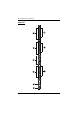
Note: Holes for ATEN Lok-U-Plug cable holders are located around the
outlets. See Securing the Cables, page 35, for further information.
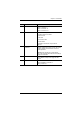
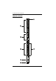
No. Item Description
1 Power Outlets* 22 in total (19 x IEC320 C13 + 3 x IEC320 C19)
Bank 1-1: Outlet 1–14; 12 x C13 + 2 x C19
Bank 1-2: Outlet 15–22; 7 x C13 + 1 x C19
2 Port and LED Panel The Port and LED panel contains:
Readout Section and LEDs
Sensor Ports
LAN Port
Door Sensor Port
Reset Switch
Full details of this section are provided on
page 23.
3 Circuit Breaker
Pushbutton
As a safety measure, if there is an over current
situation regarding the device’s power, the circuit
breakers will trip. Press the button to recover
normal operation.
Warning: See Resetting the Circuit Breaker,
page 79 for important information about resetting a
tripped circuit breaker.
4 Power Inlet The power cord that connects the unit to an AC
power source plugs into this socket.
B models connect to a NEMA 6-20P (208V)
source
G models connect to an IEC 60320 C20 source
5 Outlet Status LEDs These 8 LEDs indicate outlet status.
Lights ORANGE for powered on.
Off for powered off.
6 Output Power Indicator This LED lights steady to indicate output power for
the related bank.