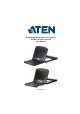
Short Depth WideScreen LCD Console CL3800 / CL3700 / CL3100 User Manual www.aten.
CL3800 / CL3700 / CL3100 User Manual EMC Information FEDERAL COMMUNICATIONS COMMISSION INTERFERENCE STATEMENT: This equipment has been tested and found to comply with the limits for a Class A digital device, pursuant to Part 15 of the FCC Rules. These limits are designed to provide reasonable protection against harmful interference when the equipment is operated in a commercial environment.
CL3800 / CL3700 / CL3100 User Manual User Information Online Registration Be sure to register your product at our online support center: International http://eservice.aten.
CL3800 / CL3700 / CL3100 User Manual User Notice All information, documentation, and specifications contained in this manual are subject to change without prior notification by the manufacturer. The manufacturer makes no representations or warranties, either expressed or implied, with respect to the contents hereof and specifically disclaims any warranties as to merchantability or fitness for any particular purpose. Any of the manufacturer's software described in this manual is sold or licensed as is.
CL3800 / CL3700 / CL3100 User Manual Package Contents CL3800 1 CL3800 USB HDMI DVI VGA Dual Rail LCD Console with Standard Rack Mount Kit 1 USB HDMI KVM Cable Set 1 Firmware Upgrade Cable 1 Power Cord 1 User Instructions* CL3700 1 CL3700 USB HDMI Single Rail LCD Console with Standard Rack Mount Kit 1 USB HDMI KVM Cable Set 1 Firmware Upgrade Cable 1 Power Cord 1 User Instructions* CL3100 1 CL3100 USB VGA Single Rail LCD Console with Standard Rack Mount Kit 1 USB VGA KVM Cable Set 1 Firmware Upgrade Cab
CL3800 / CL3700 / CL3100 User Manual Check to make sure that all of the components are present and in good order. If anything is missing, or was damaged in shipping, contact your dealer. Read this manual thoroughly and follow the installation and operation procedures carefully to prevent any damage to the console or to any other devices on the CL3800 / CL3700 / CL3100 installation. * Changes may have been made to the manual since it was published.
CL3800 / CL3700 / CL3100 User Manual Contents EMC Information . . . . . . . . . . . . . . . . . . . . . . . . . . . . . . . . . . . . . . . . . . . . ii RoHS. . . . . . . . . . . . . . . . . . . . . . . . . . . . . . . . . . . . . . . . . . . . . . . . . . . . . . ii User Information . . . . . . . . . . . . . . . . . . . . . . . . . . . . . . . . . . . . . . . . . . . . .iii Online Registration . . . . . . . . . . . . . . . . . . . . . . . . . . . . . . . . . . . . . . . .iii Telephone Support . . . . . .
CL3800 / CL3700 / CL3100 User Manual CL3700 / CL3100 . . . . . . . . . . . . . . . . . . . . . . . . . . . . . . . . . . . . . . . . 27 Operating Precautions . . . . . . . . . . . . . . . . . . . . . . . . . . . . . . . . . . . . . . . 28 LCD OSD Configuration . . . . . . . . . . . . . . . . . . . . . . . . . . . . . . . . . . . . . 29 LCD Buttons . . . . . . . . . . . . . . . . . . . . . . . . . . . . . . . . . . . . . . . . . . . . 29 Adjustment Settings . . . . . . . . . . . . . . . . . . . . . . . . .
CL3800 / CL3700 / CL3100 User Manual About this Manual This User Manual is provided to help you get the most from your CL3800 / CL3700 / CL3100 system. It covers all aspects of installation, configuration and operation. An overview of the information found in the manual is provided below. Overview Chapter 1, Introduction, introduces you to the CL3800 / CL3700 / CL3100. Its purpose, features and benefits are presented, and its components are described.
CL3800 / CL3700 / CL3100 User Manual Conventions This manual uses the following conventions: Monospaced Indicates text that you should key in. [] Indicates keys you should press. For example, [Enter] means to press the Enter key. If keys need to be chorded, they appear together in the same bracket with a plus sign between them: [Ctrl+Alt]. 1. Numbered lists represent procedures with sequential steps. ♦ Bullet lists provide information, but do not involve sequential steps.
Chapter 1 Introduction Overview The CL3800 / CL3700 / CL3100 is a Short Depth WideScreen LCD Console Series targeting limited space and mobile live streaming applications. The short depth design fits all 19" equipment cabinets, and is especially suitable for shallow racks. In addition to saving valuable space on the rack, the CL3800/ CL3700/CL3100 also provides a space-saving solution for special environments, such as outside broadcast vans (OB vans) and compact control rooms.
CL3800 / CL3700 / CL3100 User Manual The LCD monitors of the CL3800NW and CL3700NW support resolutions up to 1920 x 1080, while the LCD monitors of the CL3800NX, CL3700NX, and CL3100NX support resolutions up to 1366 x 768. See Specifications, page 47, for details. Server rooms already installed with compatible KVM switches will have the advantage of easy LCD access, an additional KVM console, and a built-in space saving sliding module, without having to purchase a new KVM switch.
Chapter 1. Introduction Features Exclusive LED illumination light – designed by ATEN to illuminate the keyboard and touchpad to allow visibility in low-light conditions Short-depth design allows you to work with your rack-mounting equipment in narrow spaces Integrated LCD KVM console with 18.
CL3800 / CL3700 / CL3100 User Manual Note: 1. Only one video signal (HDMI, DVI-D, or VGA) can be displayed at time. 2. Easy Installation Rack Mounting Kit is sold separately. Contact your ATEN dealer for product information.
Chapter 1. Introduction Requirements LCD Console The CL3800 supports most ATEN HDMI, DVI, and VGA KVM switches; the CL3700 supports most ATEN HDMI KVM switches; the CL3100 supports most ATEN VGA KVM switches. For CL3800NW and CL3700NW models, the integrated LCD monitor's maximum resolution is 1920 x 1080 @ 60 Hz; for CL3800NX, CL3700NX, and CL3100NX models, the integrated LCD monitor's maximum resolution is 1366 x 768 @ 60 Hz.
CL3800 / CL3700 / CL3100 User Manual CL3700 Length (m) Type Part Number 1.80 USB, HDMI 2L-7D02UH CL3100 6 Length (m) Type Part Number 1.20 USB, VGA 2L-5201U, 2L-5301U 1.80 2L-5202U, 2L-5302U 3.00 2L-5203U, 2L-5303U 5.
Chapter 1. Introduction Operating Systems Supported operating systems include Windows, Mac, Linux, and Sun.
CL3800 / CL3700 / CL3100 User Manual Components CL3800 Front View 1 Press the Exit/Light pushbutton for two seconds to turn the LED light ON or Off.
Chapter 1. Introduction No. Component Description 1 Upper Handle Pull to slide the LCD module out; push to slide it in. See Opening / Closing the Console, page 23, for details on sliding the console in and out 2 LCD Module After sliding the LCD module out, flip up the cover to access the LCD display. 3 LCD Controls The buttons to control the position and picture settings of the LCD display are located here. See page 29, for details.
CL3800 / CL3700 / CL3100 User Manual CL3800 Rear View 1 2 4 3 HDMI HDMI 5 No. Component Description 1 Power Socket This is a standard 3 prong AC power socket. The power cord from an AC source plugs in here. 2 Power Switch This is a standard rocker switch that powers the CL3800 on and off. 3 External Console Section For flexibility and convenience, the CL3800 supports an independent, external, KVM console.
Chapter 1. Introduction CL3700 / CL3100 Front View 1 Press the Exit/Light pushbutton for two seconds to turn the LED light ON or Off.
CL3800 / CL3700 / CL3100 User Manual No. Component 1 Upper Handle With Release Bar Pull to slide the LCD module out; push to slide it in. See Opening / Closing the Console, page 23, for details on sliding the console in and out 2 LCD Module After sliding the LCD module out, flip up the cover to access the LCD display. 3 LCD Controls The buttons to control the position and picture settings of the LCD display are located here. See page 29, for details.
Chapter 1. Introduction CL3700 Rear View 1 2 3 4 5 No. Component Description 1 Power Socket This is a standard 3 prong AC power socket. The power cord from an AC source plugs in here. 2 Power Switch This is a standard rocker switch that powers the CL3700 on and off. 3 External Console Section For flexibility and convenience, the CL3700 supports an independent, external, KVM console. The external console's USB keyboard and mouse, and HDMI cable plug in here.
CL3800 / CL3700 / CL3100 User Manual CL3100 Rear View 1 2 4 3 5 No. Component Description 1 Power Socket This is a standard 3 prong AC power socket. The power cord from an AC source plugs in here. 2 Power Switch This is a standard rocker switch that powers the CL3100 on and off. 3 External Console Section For flexibility and convenience, the CL3100 supports an independent, external, KVM console. The external console's USB keyboard and mouse, VGA monitor, and speaker cable plug in here.
Chapter 2 Hardware Setup Before you Begin 1. Important safety information regarding the placement of this device is provided on page 43. Please review it before proceeding. 2. Make sure that power to all the devices you will be connecting up has been turned off. You must unplug the power cords of any computers that have the Keyboard Power On function. 3. (CL3800 only) Packing material has been inserted to protect the CL3800 during shipping.
CL3800 / CL3700 / CL3100 User Manual 4. The LCD KVM switch is designed for rack mounting. If the KVM switch is not rack mounted be sure to place it on a completely flat and firm surface before pulling the device in or out to prevent damage due to uneven force on the module.
Chapter 2. Hardware Setup Standard Rack Mounting A standard rack mounting kit enables the CL3800 to be mounted in a rack with a depth of 47–75 cm. A standard rack mounting kit enables the CL3700/ CL3100 to be mounted in a rack with a depth of 42-72 cm. L Bracket R Bracket Note: 1. It takes two people to mount the module: one to hold it in place, the other to screw it in. 2. The standard rack mounting kit does not include screws or cage nuts.
CL3800 / CL3700 / CL3100 User Manual To rack mount the CL3800 / CL3700 / CL3100, do the following: 1. Attach the left and right mounting brackets to the back of the rack, installing four screws in the tabs to secure them in place. 2. While one person inserts the CL3800 / CL3700 / CL3100 into place by sliding its left and right side bars into the mounting brackets (on the rack), have a second person install four screws in the front tabs to secure the module to the front of the rack.
Chapter 2. Hardware Setup Connecting Up - CL3800 Refer to the example installation diagram in the next page as you perform the following steps: 1. Plug the USB; then HDMI, DVI-D, or VGA and audio connectors of a KVM cable (either supplied with the unit, or purchased separately, see Cables, page 5) into the KVM ports located in the CPU section on the rear of the CL3800. Note: The CL3800 supports speakers only. It does not support a microphone.
CL3800 / CL3700 / CL3100 User Manual Installation Diagram 20
Chapter 2. Hardware Setup Connecting Up - CL3700 Refer to the example installation diagram below as you perform the following steps: 1. Plug the HDMI and USB Type B connectors of a KVM cable into the KVM ports located in the CPU section on the rear of the CL3700. 2. Plug the USB Type A and HDMI connectors of the KVM cable into their respective ports of a computer. 3.
CL3800 / CL3700 / CL3100 User Manual Connecting Up - CL3100 Refer to the example installation diagram below as you perform the following steps: 1. Plug the VGA and audio connectors of a KVM cable into the KVM ports located in the CPU section on the rear of the CL3100. Note: The CL3100 supports speakers only. It does not support a microphone. Connect the KVM cable’s speaker jack (green) to the CL3100’s audio port. 2.
Chapter 3 Operation Opening / Closing the Console The CL3800's console consists of two modules: an 18.5” LCD display module located under the top cover; and a keyboard / touch pad module below the LCD module. The modules can either slide together, or independently. This allows you to have the LCD display available for viewing while the keyboard / touch pad module is conveniently out of the way when not in use.
CL3800 / CL3700 / CL3100 User Manual 2. Pulling, slide the Panel module out until it clicks in place. 3. Raise the top panel all the way back to expose the LCD screen.
Chapter 3. Operation 4. Use the Lower Release Bar handle to pull the keyboard module straight out unit it clicks in place. Lower Release Bar 5. To independently retract the keyboard into the rack, slide both Keyboard Module Releases and push the keyboard module all the way in.
CL3800 / CL3700 / CL3100 User Manual 6. Slide the keyboard in until it's completely inserted into the rack. 7. To close the LCD screen, lower the panel module until it lies flat and slide it back in.
Chapter 3. Operation CL3700 / CL3100 Refer to the diagrams below to open or close the console as you do the following: 1. Pull on the Release Bar on the upper handle. Slide the console module out until it clicks in place, and then raise the LCD Module lid. 2. To close the console, lower the LCD Module until it lies flat, and slide the full console in.
CL3800 / CL3700 / CL3100 User Manual Operating Precautions The maximum load bearing capacity of the keyboard module is 30 kg. Failure to heed the information below can result in damage to the keyboard module. Right! Rest your hands and arms lightly on the keyboard module as you work. Wrong! DO NOT lean your body weight on the keyboard module. DO NOT place heavy objects on the keyboard module.
Chapter 3. Operation LCD OSD Configuration LCD Buttons The LCD OSD allows you to set up and configure the LCD display. Four buttons are used to perform the configuration, as described in the table, below: Button MENU Function When you have not entered the LCD OSD Menu function, pressing this button invokes the Menu function, and brings up the Main Menu.
CL3800 / CL3700 / CL3100 User Manual Adjustment Settings An explanation of the LED OSD adjustment settings is given in the table below: Setting Brightness Explanation Adjusts the background black level of the screen image. Contrast Adjusts the foreground white level of the screen image. Phase If pixel jitter or horizontal line noise is visible on the display, your LED may have the wrong phase setting. Adjust the phase setting to eliminate these problems.
Chapter 3. Operation Hot Plugging The CL3800 / CL3700 / CL3100 supports hot plugging – components can be removed and added to the console by unplugging their cables from the ports without the need to shut down the CL3800 / CL3700 / CL3100. Powering Off and Restarting If it becomes necessary to Power Off the CL3800 / CL3700 / CL3100 (to upgrade the firmware, for example), simply turn off the power to the unit using the rear panel power switch.
CL3800 / CL3700 / CL3100 User Manual Hotkeys Console selection is accomplished with the following hotkey combinations: Combination Action Beeps LEDs [Ctrl] [Alt] [Shift] [P] [C] [Enter] To select normal mode (pc, etc.). 2 None [Ctrl] [Alt] [Shift] [M] [A] [C] [Enter] To select Mac 2 None [Ctrl] [Alt] [Shift] [S] [U] [N] [Enter] To select SUN 2 None [Ctrl] [Alt] [Shift] Activates the Firmware Upgrade Mode.
Chapter 3. Operation 3. Either side of the keyboard can be used to invoke [Shift] [Ctrl] [Alt] hotkeys. 4. If the KVM switch connected to the CL3800 / CL3700 / CL3100 uses the [Ctrl] [Alt] [Shift] combination to invoke its hotkey mode, you won't be able to access any of its hotkey operations because the CL3800 / CL3700 / CL3100 will capture the combination for console selection first.
CL3800 / CL3700 / CL3100 User Manual This Page Intentionally Left Blank 34
Chapter 4 Firmware Upgrade The Firmware Upgrade Utility As new firmware revisions become available for the CL3800 / CL3700 / CL3100, firmware upgrade packages are posted on the ATEN web site. The Windows-based Firmware Upgrade Utility (FWUpgrade.exe) provides a smooth, automated process for upgrading the CL3800 / CL3700 / CL3100’s firmware. Check the web site regularly to find the latest firmware packages and information relating to them.
CL3800 / CL3700 / CL3100 User Manual Firmware Upgrade Mode The CL3800 / CL3700 / CL3100’s firmware upgrade mode can be accessed one of two ways: by entering a hotkey sequence (see Hotkeys, page 32), or by placing the CL3800 / CL3700 / CL3100 in firmware upgrade recovery mode (see Firmware Upgrade Recovery, page 41). Note: In order to activate the Firmware Upgrade Mode using a hotkey sequence, the Firmware Upgrade Recovery Switch (see page 9) must be set to the Normal position. 1.
Chapter 4. Firmware Upgrade Performing the Upgrade Starting the Upgrade: 1. With the CL3800 / CL3700 / CL3100 in Firmware Upgrade Mode, run the downloaded Firmware Upgrade Package file from your computer - either by double clicking the file icon, or by opening a command line and keying in the full path and filename. The Firmware Upgrade Utility Welcome screen appears: 2. Read and Agree to the License Agreement (enable the I Agree radio button). (Continues on next page.
CL3800 / CL3700 / CL3100 User Manual (Continued from previous page.) 3. Click Next. The Firmware Upgrade Utility main screen appears: The Utility inspects your installation. All the devices capable of being upgraded by the package are listed in the Device List panel. 4. Click Next to perform the upgrade. If you enabled Check Firmware Version, the Utility compares the device's firmware level with that of the upgrade files.
Chapter 4. Firmware Upgrade Upgrade Succeeded: After the upgrade has completed, a screen appears to inform you that the procedure was successful: Click Finish to close the Firmware Upgrade Utility.
CL3800 / CL3700 / CL3100 User Manual Upgrade Failed: If the upgrade failed to complete successfully the Upgrade Failed screen appears: Click Cancel to close the Firmware Upgrade Utility. See the next section, Firmware Upgrade Recovery, for how to proceed.
Chapter 4. Firmware Upgrade Firmware Upgrade Recovery There are three conditions that call for firmware upgrade recovery: When the unit’s firmware becomes corrupted for some reason and you are unable to operate it. When a firmware upgrade procedure is interrupted. When a firmware upgrade procedure fails. To perform a firmware upgrade recovery, do the following: 1. Power off the CL3800 / CL3700 / CL3100. 2. Connect the Firmware Upgrade Cable to its Firmware Upgrade Port. 3.
CL3800 / CL3700 / CL3100 User Manual This Page Intentionally Left Blank 42
Appendix Safety Instructions General This product is for indoor use only. Read all of these instructions. Save them for future reference. Follow all warnings and instructions marked on the device. Do not place the device on any unstable surface (cart, stand, table, etc.). If the device falls, serious damage will result. Do not use the device near water. Do not place the device near, or over, radiators or heat registers.
CL3800 / CL3700 / CL3100 User Manual If an extension cord is used with this device make sure that the total of the ampere ratings of all products used on this cord does not exceed the extension cord ampere rating. Make sure that the total of all products plugged into the wall outlet does not exceed 15 amperes. To help protect your system from sudden, transient increases and decreases in electrical power, use a surge suppressor, line conditioner, or uninterruptible power supply (UPS).
Appendix Rack Mounting Before working on the rack, make sure that the stabilizers are secured to the rack, extended to the floor, and that the full weight of the rack rests on the floor. Install front and side stabilizers on a single rack or front stabilizers for joined multiple racks before working on the rack. Always load the rack from the bottom up, and load the heaviest item in the rack first. Make sure that the rack is level and stable before extending a device from the rack.
CL3800 / CL3700 / CL3100 User Manual Technical Support International For online technical support – including troubleshooting, documentation, and software updates: http://support.aten.com For telephone support, see Telephone Support, page iii. North America Email Support Online Technical Support support@aten-usa.com Troubleshooting Documentation Software Updates Telephone Support http://www.aten-usa.
Appendix Specifications CL3800NW / CL3800NX Function CL3800NW CL3800NX Computer Connections Direct Console Selection 1 Hotkey Connectors External Console Ports 1 x HDMI Female 1 x DVI-D Female (White) 1 x HDB-15 Female (Blue) 2 x USB Type A Female 1 x 3.5 mm Audio Jack Female (Green) KVM Ports 1 x HDMI Female 1 x DVI-D Female (White) 1 x HDB-15 Male (Blue) 1 x USB Type B Female 1 x 3.5 mm Audio Jack Female (Green) USB Port 1 x USB Type A Female Firmware Upgrade Power 1 x 3.
CL3800 / CL3700 / CL3100 User Manual Function CL3800NW CL3800NX Resolution 1920 x 1080 @ 60 Hz 1366 x 768 @ 60 Hz Pixel Pitch 0.213 mm x 0.213 mm 0.3 mm x 0.3 mm Response Time 20 ms 5 ms Viewing Angle 178° (H), 178° (V) 170° (H), 160° (V) Contrast Ratio 1000:1 1000:1 Support Color 16.7M colors 16.7M colors 350 cd/m² 250 cd/m² Luminance Emulation Keyboard / Mouse Maximum Input Power Rating Power Consumption USB 100–240V AC; 50–60Hz; 1A 110V, 26.6W / 220V, 26.8W 110V, 18.
Appendix CL3700NW / CL3700NX Function CL3700NW CL3700NX Computer Connections Direct 1 Console Selection Hotkey Connectors External Console Ports 1 x HDMI Female 2 x USB Type A Female KVM Ports 1 x HDMI Female 1 x USB Type B Female USB Port 1 x USB Type A Female Firmware Upgrade 1 x 3.
CL3800 / CL3700 / CL3100 User Manual Function CL3700NW CL3700NX Contrast Ratio 1000:1 1000:1 Support Color 16.7M colors 16.7M colors 350 cd/m² 250 cd/m² Luminance Maximum Input Power Rating Power Consumption 100–240 V AC, 50–60 Hz, 1 A 110V, 23.3W / 220V, 23.9W 110V, 13.6W / 220V, 13.5W Environmental 0–40o C Operating Temperature -20–60o C Storage Temperature Humidity 0–80% RH Non-condensing Physical Properties Housing Weight Metal + Plastic 9.01 kg 9.03 kg Dimensions (L x W x H) 48.
Appendix CL3100NX Function CL3100NX Computer Connections Direct Console Selection 1 Hotkey Connectors External Console Ports 1 x HDB-15 Female (Blue) 2 x USB Type A Female 1 x 3.5 mm Audio Jack Female (Green) KVM Ports 1 x SPHD Female (Yellow) 1 x 3.5 mm Audio Jack Female (Green) USB Port 1 x USB Type A Female Firmware Upgrade Power 1 x 3.
CL3800 / CL3700 / CL3100 User Manual Function CL3100NX Viewing Angle 170° (H), 160° (V) Contrast Ratio 1000:1 Support Color 16.7M colors Luminance Maximum Input Power Rating Power Consumption 250 cd/m² 100–240 V AC, 50–60 Hz, 1 A 110V, 13.8W / 220V, 14.1W Environmental Operating Temperature Storage Temperature Humidity 0–40o C -20–60o C 0–80% RH Non-condensing Physical Properties Housing Weight Metal + Plastic 9.07 kg Dimensions (L x W x H) 48.06 x 47.70 x 4.
Appendix Optional Rack Mounting For convenience and flexibility, three optional rack mounting kits for the CL3800 are available as shown in the following table: Bracket Type Size (cm) Easy Installation – Short (2X-041G) 45.0—70.0 Easy Installation – Long (2X-042G) 68.0—105.0 Three optional rack mounting kits for the CL3700 and CL3100 are available as shown in the following table: Bracket Type Size (cm) Easy Installation – Short (2X-041G) 42.0—70.0 Easy Installation – Long (2X-042G) 68.0—105.
CL3800 / CL3700 / CL3100 User Manual 2. Attach the left and right easy-installation mounting rails to the inside of the rack. The flange that supports the CL3800 / CL3700 / CL3100 will be to the inside. Rear Flang Slide bar Rear Attachment Sliding Bracket Front Flang Support Flang Left Rail Right Rail a) Screw the front flanges to the rack first. b) Slide the bars with the rear flanges toward the rack until the flanges make contact with the rack, then screw the rear flanges to the rack.
Appendix 3. Slide the CL3800 / CL3700 / CL3100 onto the support flanges. Use the screws supplied with this package to loosely attach the front of the CL3800 / CL3700 / CL3100 to the front of the rack (only tighten the screws part way). 4. Slide the rear attachment sliding brackets along the slide bars until they contact the rear of the CL3800 / CL3700 / CL3100, then use the screws supplied with this package to attach the bars to the rear of the CL3800 / CL3700 / CL3100 (tighten the screws all the way).
CL3800 / CL3700 / CL3100 User Manual 5. Slide the CL3800 / CL3700 / CL3100 open and closed a couple of times to be sure that it is properly aligned and operating smoothly. (See Opening / Closing the Console, page 23, for opening and closing procedures.) 6. After determining that the CL3800 / CL3700 / CL3100 is lined up and operating correctly, finish by fully tightening the front attachment screws inserted in Step 3.
Appendix Sun Keyboard Emulation The PC compatible (101/104 key) keyboard can emulate the functions of the Sun keyboard when the Control key [Ctrl] is used in conjunction with other keys. The corresponding functions are shown in the table below.
CL3800 / CL3700 / CL3100 User Manual Mac Keyboard The PC compatible (101/104 key) keyboard can emulate the functions of the Mac keyboard. The emulation mappings are listed in the table below.
Appendix Troubleshooting Symptom Action There are ghost images on the external monitor. The distance between the external console and the CL3800 is too great. The maximum DVI cable distance should not exceed 20 m and, in some cases, may need to be shorter. Replace the DVI cable with one of an appropriately short length. Some characters I enter from the keyboard do not display correctly. The keyboard layout setting for the port does not match the keyboard you are using.
CL3800 / CL3700 / CL3100 User Manual Limited Warranty ATEN warrants its hardware in the country of purchase against flaws in materials and workmanship for a Warranty Period of two [2] years (warranty period may vary in certain regions/countries) commencing on the date of original purchase. This warranty period includes the LCD panel of ATEN LCD KVM switches. Select products are warranted for an additional year (see A+ Warranty for further details).
Index A AC Power Models Specifications, 47 C Connecting Up, 19, 21 Console Selection, 32 F Features, 3 Firmware upgrade cable, 35 Mode, 36 recovery, 41 utility, 35 H Hot Plugging, 31 K Keyboard Emulation, 57 Mac, 58 KL1100 Front View, 8, 11 Rear View (AC Power), 10 L LCD Buttons, 29 OSD configuration, 29 O Online Registration, iii Opening the Console, 23 Operating Precautions, 28 P Port ID Numbering & Selection, 31 Powering Off, 31 Precautions, 28 R Rack Mounting Optional, 53 Standard, 17 Reset Swi