User Manual CS-1004 CS-1008 CS-1016 2001-06-9
NOTE: This equipment has been tested and found to comply with the limits for a Class B digital device pursuant to Subpart J of Part 15 of FCC Rules. These limits are designed to provide reasonable protection against harmful interference in a residential installation. This equipment generates, uses and can radiate radio frequency energy and, if not installed and used in accordance with the instructions, may cause harmful interference to radio communications.
Packing List The complete Master View package consists of: ! One Master View KVM Switch (CS-1004, CS-1008, or CS-1016) ! One Power Adapter ! One User Manual Check to make sure that the unit was not damaged in shipping. If you encounter a problem, contact your dealer. Read this manual thoroughly and follow the installation and operation procedures carefully to prevent any damage to the unit, and/or any of the devices connected to it. ©Copyright 2000 ATEN International Co., Ltd. Manual Part No.
Contents Overview . . . . . . . . . . . . . . . . . . . . . . . . . . . . . . . . . . . . . . . . . . . . . . . . . . . . . . 1 Features . . . . . . . . . . . . . . . . . . . . . . . . . . . . . . . . . . . . . . . . . . . . . . . . . . . . . . . 2 Hardware Requirements . . . . . . . . . . . . . . . . . . . . . . . . . . . . . . . . . . . . . . . . . . 3 Console . . . . . . . . . . . . . . . . . . . . . . . . . . . . . . . . . . . . . . . . . . . . . . . . . . . . 3 PC . . . . . . . . . . . . . . . . . . .
Overview The Master View KVM Switch is a control unit that allows access to multiple computers from a single console (keyboard, monitor, and mouse). Before the development of the Master View, the only way to control multiple computer configurations from a single console was through a complex and costly network system. Now, with the Master View, you can easily access multiple computers in a cost effective manner. Depending on the model a Master View unit can control up to 4, 8, or 16 computers.
Features ! Special ASIC Technology - Enhances Compatibility and Reliability ! Daisy Chain Up To 31 Additional Units - Control Up to 128, 256, or 512 Computers From a Single Console ! No Software Required - Computer Selection via Front Panel Switches or OSD ! Broadcast Function - Used to Install Software on Multiple Computer Systems or Shut Them All Down.
Hardware Requirements Console ! A VGA, SVGA, or Multisync monitor capable of the highest resolution that you will be using on any computer in the installation. ! A PS/2 style mouse ! A PS/2 style keyboard PC The following equipment must be installed on each computer: ! A VGA, SVGA or Multisync card. ! Either a 6-pin mini-DIN (PS/2 style), or DB-9 (standard serial), mouse port.
Cables For optimum signal integrity and to simplify the layout, we strongly recommend that you use the following high quality CS Custom Cable sets: Connector Type AT (5 pin DIN) Keyboard and Serial Mouse PS/2 (6 pin mini-DIN) Keyboard and Mouse Daisy Chained Units CS Custom Cable 2L-1701P + Keyboard & Mouse Adapters 2L-1701P 2L-1700 Note: The keyboard and the mouse cables have PS/2 style connector at each end: ! If your computer uses a standard AT style keyboard socket and standard 9 pin serial ports, yo
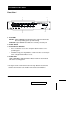
Introduction Front View * 1 2 K/M Reset 4 3 1. Port LEDs OnLine: Lights ORANGE to indicate that the computer attached to the corresponding port is up and running Selected: Lights GREEN to indicate the currently selected port. 2. Power Switch 3. Port Selection Switches ! Press a switch to access the computer attached to the corresponding port. ! Simultaneously pressing Switches 1 and 2 for three seconds performs a Keyboard and Mouse reset. 4.
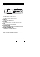
Rear View * 1 3 4 5 2 6 7 1. Daisy Chain Selection If you daisy chain units, the cables plug in here. 2. CPU Port Section The cables that link to the computers plug in here. 3. Power Jack The power adapter cable plugs in here 4. DIP Switch SW 1 - 5: Sets the Station No. (see the table on page 25 for details) 5. Link Link is reserved and has no function at this time. 6. Console Port Section If this is a first station unit, your monitor, keyboard and mouse plug in here. 7.
Installation Before you Begin 1. Make sure that power to all the devices you will be connecting up have been turned off. You must unplug the power cords of any computers that have the Keyboard Power On function. Otherwise, the switch will receive power from the computer. 2. To prevent damage to your equipment due to ground potential difference, make sure that all devices on the installation are properly grounded. Consult your dealer for technical details, if necessary.
4. Plug the power adapter into an AC source; plug the power adapter cable into the Master View’s Power Jack. 5. Turn on the power to the Master View. When you turn the unit On, it undergoes a Power On Self Test.
Daisy Chaining To control even more computers, up to 31 additional Master View units can be daisy chained from the Chain port of the First Stage unit. The daisy chained Master Views that connect back to the First Stage unit are considered Second Stage units. As many as 8 (CS-1004), 16 (CS-1008) or 32 (CS-1016) computers can be controlled in a complete two stage installation.
PS/2 MOUSE VGA MONITOR PS/2 KEYBOARD 6. Connect the computers to the ports with the cable sets described in the Cables section on page 4, and power up. When powering up, you must follow these two basic rules: a) Turn on the power to a child Master View Station before turning on the power to its parent (i.e., start with the last unit in the chain and work back to the First Station). b) Turn on the power to all the Master View Stations before turning on the power to any of the computers.
Operation Hot Plugging The Master View supports hot plugging - components can be removed and added back into the installation by unplugging their cables from the CPU ports without the need to shut the unit down. In order for hot plugging to work properly, however, these procedures must be followed: ! Hot Plugging CPU Ports: When hot plugging cables from the CPU ports: a) The cable must be plugged back into the same port it was removed from. b) The mouse cable must be plugged in before the keyboard cable.
Powering On / Off and Restarting ! Power On Turn the power to the Master View before turning on the power to the computers. ! Power Off If it becomes necessary to Power Off one of the Master View units, before starting it back up you must do the following: 1. Shut down all the computers that are attached to the unit, as well as all the stations and all the computers that are daisy chained down from it (all the child stations and the computers attached to them). Note: 1.
Port Selection The Master View provides two methods to obtain instant access to any computer in your installation: Manual and OSD. ! Manual Simply press the appropriate Port Selection Switch on the Master View’s front panel. After you press the switch, the Selected LED lights to indicate that the port is currently selected. The OSD (see p.14) automatically switches to highlight the computer that you have selected. Note: 1.
OSD Operation OSD Overview On Screen Display (OSD), provides a menu driven interface to handle the computer switching procedure. Using OSD is a great deal more convenient - especially in large, daisy chained installations where it is difficult to keep track of which port a particular computer is attached to. All operations start from the OSD Main Menu. To pop up the Main Menu, tap the left Ctrl key OR the right Ctrl key twice. Note:1. The keys must be on the same side (both left or both right). 2.
Port Numbering Each computer on a Master View installation has a two part Port Number (PN). The first part (in front of the dash) represents the Master View Station number; the second part (after the dash) represents the port number on the Master View that the computer is attached to. For example, a computer attached to port 11 of a fifth stage Master View would have a port number of 05-11.
OSD Main Menu Headings Heading Explanation SN-PN This column lists the Port ID numbers (Station Number - Port Number) for all the CPU ports on the installation. The simplest method to access a particular computer is move the Highlight Bar to it, then press [Enter]. QV If a port has been selected for Quick View scanning (see F2 and F4, below), an arrowhead displays in this column to indicate so. PC Lists all the computers that are Powered On and are On Line.
! F2 SCAN: Pressing [F2] initiates Quick View Scanning, in which the OSD cycles through all the ports that are currently selected in the List view (see F3, below), and displays each one for the amount of time set with the Scan Duration setting under the F6 SET function (see p. 19). When you want to stop at a particular location, press the [Spacebar] to stop scanning. Note: 1.
To make a choice move the Highlight Bar to the choice you want, then press [Enter]. An icon appears before the choice to indicate that it is the currently selected one. Note: 1. You can access any port on any list by using the Navigation Keys then pressing [Enter]. 2. If you select a port that does not have a computer attached to it, or if the attached computer is powered Off, the OSD will still switch to it, and will not show an error.
! F6 SET: Pressing [F6] brings up the OSD configuration menu. To change a setting: a) Move the highlight bar to the choice you want, then press [Enter]. b) On the submenu that appears, move the highlight bar to the choice you want and press [Enter]. An icon of a pointing finger indicates which choice is the currently selected one.
Setting 20 Function OSD ACTIVATING HOTKEY Selects which Hotkey activates the OSD function: [Ctrl] [Ctrl] or [Scroll Lock] [Scroll Lock]. The default is the Ctrl key combination, but this may conflict with programs running on the computers, in which case, the Scroll Lock option should be used. LOCK CONSOLE (TOGGLE) Locks / Unlocks the Console. When the Console is locked, only the current monitor screen displays.
Setting Function CLEAR NAME LIST* Clears all Port Names from the Name List. You are asked to confirm before the procedure goes on. Key in Y, then press [Enter] to confirm. While the names are being cleared, a message appears on the display to indicate so. After the names have been cleared, another message appears to indicate that the procedure is completed successfully.
! F7 BRDCST (Broadcast Mode): Broadcast Mode is used to perform the same operation on all active computers at the same time. This function is particularly useful for installing/updating software, or shutting the entire installation down. To invoke Broadcast Mode, activate the OSD (if it is not already active) and do the following: 1. Press [F7] A Broadcast symbol appears in front of the Port ID (if the Port ID is currently displayed on the screen), to indicate that Broadcast Mode is in effect. 2.
Factory Default Settings The factory default settings are as follows: Setting Default Display Duration 3 Seconds Display Mode The Station Number plus the Port Number Scan Duration 3 Seconds OSD Security In order to prevent unauthorized access to the computers, the OSD provides a password security feature. If a password has been set, the OSD will request that the user specify it before allowing entry. To set a password: 1. Press [F6] to bring up the setup configuration menu. 2.
Appendix Master View - Computer Connection Table The following table indicates the relationship between the number of Master View Units and the number of computers that they control: MVs 24 Computers MVs Computers MVs Computers MVs Computers 1 8 20 134 - 141 39 267 - 274 58 400 - 407 2 8-15 21 141 - 148 40 274 - 281 59 407 - 414 3 15 - 22 22 148 - 155 41 281 - 288 60 414 - 421 4 22 - 29 23 155 - 162 42 288 - 295 61 421 - 428 5 29 - 36 24 162 - 169 43 295 - 302
Station Numbering Table The first Master View (the one that the console connects to), is considered the First Station; the Master View that daisy chains to it is considered the Second Station; the Master View daisy chained to the Second Station is considered the Third Station, etc.
Troubleshooting Symptom Possible Cause Mouse not responding. Improper mouse reset. Port LEDs 1-4 flash repeatedly Power On Self Test problem 26 Action 1. Reset the mouse (and keyboard) by simultaneously pressing Buttons 1 and 2 on the First Stage unit for 3 seconds. 2. Unplug the mouse connector from the Console Mouse Port, then plug it back in. See the information on p.
Specifications Function Computer Connections CS-1004 CS-1008 CS-1016 Direct 4 8 16 Max. (Daisy Chain) 128 256 512 Max Master View Stations 32 Port Selection Front Panel Switches, Hot Keys, OSD LEDs Power(Orange) 1 1 1 On Line (Orange) 4 8 16 Selected (Green) 4 8 16 Keyboard 1 x 6 pin mini-DIN female Mouse 1 x 6 pin mini-DIN female Video 1 x 15 pin HDB female Microphone Jack 1 Speaker Jack 1 Console Connectors Power Consumption (max.) Switches DC 9V; 4.5W DC 9V; 6.
Limited Warranty IN NO EVENT SHALL THE DIRECT VENDOR’S LIABILITY EXCEED THE PRICE PAID FOR THE PRODUCT FROM THE DIRECT, INDIRECT, SPECIAL, INCIDENTAL OR CONSEQUENTIAL DAMAGES RESULTING FROM THE USE OF THE PRODUCT, DISK OR ITS DOCUMENTATION. The direct vendor makes no warranty or representation, expressed, implied, or statutory with respect to the contents or use of this documentation, and specially disclaims its quality, performance, merchantability, or fitness for any particular purpose.