8 Port KVM Switch User Manual CS-128A
Packing List The complete Master View Pro package consists of: w One CS-128A KVM Switch w One Power Adapter w One User Manual Check to make sure that the unit was not damaged in shipping. If you encounter a problem, contact your dealer. Please read this manual thoroughly and follow the installation and operation procedures carefully to prevent any damage to the unit, and/or any of the devices connected to it. ©Copyright 2000 ATEN™ International Co., Ltd. Manual Part No.
Contents Overview . . . . . . . . . . . . . . . . . . . . . . . . . . . . . . . . . . . . . . . . . . . . . . . . . . . . . . . . . . . . . . 1 Features . . . . . . . . . . . . . . . . . . . . . . . . . . . . . . . . . . . . . . . . . . . . . . . . . . . . . . . . . . . . . . . 2 Hardware Reqirements . . . . . . . . . . . . . . . . . . . . . . . . . . . . . . . . . . . . . . . . . . . . . . . . . . . 3 Console . . . . . . . . . . . . . . . . . . . . . . . . . . . . . . . . . . . . . . . . . . . . . . . . .
Overview The Master View CS-128A KVM Switch is a control unit that allows access to multiple computers from a single console (keyboard, monitor, and mouse). Before the development of the Master View, the only way to control multiple computer configurations from a single console was through a complex and costly network system. Now, with the Master View CS-128A, you can easily access multiple computers in a cost effective manner. A single Master View CS-128A can control up to 8 computers.
Features w Cascadable To Three Levels - Control Up to 512 computers From a Single Console w No Software Required - Computer Selection via Front Panel Switches, Hot Keys, or OSD (On Screen Display) w Quick View Scan Feature for Monitoring Selected Computers w PS/2 and Serial Mouse Emulation For System Bootup w Console’s PS/2 Mouse Controls All Connected Computers - Even Those With Serial Mice w PS/2 Compatible Mouse Support - Microsoft Intellimouse Explorer and Logitech FirstMouse+ Support* w SV
Hardware Reqirements Console w A VGA, SVGA, or Multisync monitor capable of the highest resolution that you will be using on any computer in the installation. w A PS/2 style mouse w A PS/2 style keyboard PC w The following equipment must be installed on each computer: w A VGA, SVGA or Multisync card. w Either a 6-pin mini-DIN (PS/2 style), or DB-9 (standard serial), mouse port.
Introduction Front View 1 2 3 4 5 1. Port LEDs On Line: Lights ORANGE to indicate that the computer attached to the corresponding port is up and running. If the LED is flashing, it indicates that the Port is being used for Cascading to another Master View switch. Selected: Lights GREEN to indicate the currently selected port. The LED is steady under normal conditions, but flashes when its port is accessed under Auto Scan mode. 2. Auto Scan Button Pressing this button starts Auto Scan Mode. 3.
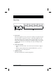
Rear View: 1 2 3 1. Power Jack The unit is designed to be non-powered (no external power required). It gets its power from the computers it connects to. Generally speaking, the only time that external power is required is when you daisy chain it, or if operation becomes erratic because the unit isn’t obtaining enough power from the computer. If you choose to use external power, the power adapater cable plugs in here. 2.
Installation Before you Begin 1. Make sure that power to all the devices you will be connecting up have been turned off. You must unplug the power cords of any computers that have the Keyboard Power On function. Otherwise, the switch will receive power from the computer. 2. To prevent damage to your installation due to ground potential difference, make sure that all devices on the installation are properly grounded. Consult your dealer for technical details, if necessary.
4. Turn on the power to the computers. Note: If you choose to use external power, the CS-128A must be plugged in and receiving power before turning on the power to the computers. Two Stage Installation To control even more computers, up to eight additional CS-128A units can be cascaded from the CPU ports of the First Stage unit. The cascaded Master Views are considered Second Stage units. As many as 64 computers can be controlled in a complete two stage installation.
Three Stage Installation The procedures for setting up a three stage installation are essentially the same as for a two stage installation. With a three stage setup, as many as 512 computers can be controlled in a complete installation. A table showing the relation between the number of computers and the number of Master View units needed to control them is provided in the Appendix. Note: Master View units cannot be cascaded beyond the third level. To set up a three stage installation, do the following: 1.
4. Repeat steps 1 - 3 for any other Third Stage units you wish to connect. 5. For each Third Stage unit, plug the power adapter cable into the Master View’s Power Jack; plug the power adapter into an AC source. 6. Plug in the power adapters for all the Second Stage Master View units. 7. Plug in the power adapter for the First Stage Master View unit. 8. Turn on the power to all the computers. Note: The Power On sequence requires that all Third Stage units be powered on first.
Operation Hot Plugging The Master View CS-128A supports hot plugging - components can be removed and added back into the installation by unplugging their cables from the CPU ports without the need to shut the unit down. In order for hot plugging to work properly, however, these procedures must be followed: w Hot Plugging CPU Ports: CPU port cables must be plugged back into the exact same ports they were removed from.
Powering Off and Restarting If it becomes necessary to Power Off one of the Master View units, before starting it back up you must do the following: 1. Shut down all the computers that are attached to it, as well as all the stations and all the computers that are daisy chained down from it (all the child stations and the computers attached to them). Note: 1. You must unplug the power cords of any computers connected to the powered off Master View that have the Keyboard Power On function.
Port Selection The Master View CS-128A provides three methods to obtain instant access to any computer in your installation: Manual; Hotkey; and OSD (On Screen Display). w Manual Simply press the appropriate Port Selection Switch on the Master View’s front panel. After you press the switch, the Selected LED lights to indicate that the port is currently selected. The OSD (see p. 15) automatically switches to highlight the computer that you have selected. Note: 1.
Port ID Numbering ID Numbering Overview Each CPU Port on a Master View installation is assigned a unique Port ID. You can directly access any computer on any level of the installation by specifying the Port ID of the CPU Port that the computer is connected to - either with the Hotkey port selection method, or from the OSD. The Port ID is a one, two, or three digit number that is determined by the Stage Level and CPU Port number of the Master View unit that the computer is connected to.
Port Key In Examples 1. To access a computer attached to Port 3 of a Single Stage installation, key in 3 for the Port ID, as follows: [Ctrl]+[Alt]+[Shift] 3 [Enter] 2. To access a computer attached to Port 3 of a Second Stage unit that is cascaded down from Port 2 of the First Stage unit, keyin 23 for the Port ID, as follows: [Ctrl]+[Alt]+[Shift] 2 3 [Enter] Note: You must key in the numbers one at a time. 3.
OSD Operation OSD Overview OSD (On Screen Display), provides a menu driven interface to handle the computer switching procedure. Although Hotkey switching still works, using OSD is a great deal more convenient - especially in large, daisy chained installations where it is difficult to keep track of which port a particular computer is attached to. All operations start from the OSD Main Menu. To pop up the Main Menu, tap either Ctrl key twice. Note: 1.
OSD Menu Navigation w [Esc] cancels the current selection, or dismisses the current menu and moves back to the menu one level above. If you are at the highest menu level, it deactivates OSD. w Use the Up and Down Arrow Keys or click on the Up and Down Triangle symbols (st) to move up or down through the list one line at a time. w Use [Pg Up] and [Pg Dn] or click on the Up and Down Arrow symbols (ÇÈ) to move up or down through the list one screen at a time.
OSD Main Menu Headings Heading Explanation PN This column lists the Port ID numbers (Station Number - Port Number) for all the CPU Ports on the installation. The simplest method to access a particular computer is move the Highlight Bar to it, then press [Enter]. QV If a port has been selected for Quick View scanning (see F2 and F4, below), an arrowhead displays in this column to indicate so. PC Lists all the computers that are Powered On and are On Line.
w F2 Scan: Pressing [F2] initiates Quick View Scanning, in which the OSD cycles through all the ports that are currently selected in the List view (see F3, below), and displays each one for the amount of time specified with the Set Scan Duration setting under the F6 SET function (see p. 20). When you want to stop at a particular location, press the [Spacebar] to stop scanning. Note: 1.
Move the Highlight Bar to the choice you want, then press [Enter]. An icon appears before the choice to indicate that it is the currently selected one. Note: 1. You can access any port on any list by using the Navigation Keys then pressing [Enter]. 2. If you select a port that does not have a computer attached to it, or if the attached computer is powered Off, the OSD will still switch to it, and will not show an error.
w F6 Set: Pressing [F6] brings up the OSD configuration menu. To change a setting: 1. Move the highlight bar to the choice you want, then press [Enter]. 2. On the submenu that appears next, move the highlight bar to the choice you want and press [Enter]. An icon of a pointing finger indicates which choice is the currently selected one.
Setting Function SET PASSWORD Allows you to set a password in order to control access to: Clearing the Name List; Restoring Default Values; and Locking/Unlocking the Console. See the OSD Security Features section, below, for password setting details. CLEAR THE NAME LIST* Clears all Port Names from the Name List. You are asked to confirm before the procedure goes on. Key in Y, then press [Enter] to confirm. While the names are being cleared, a message appears on the display to indicate so.
Factory Default Settings The factory default settings are as follows: Setting Default Display Duration Always On Display Mode The Port Number plus the Port Name Scan Duration 3 Seconds OSD Security In order to prevent unauthorized access to the computers, the OSD provides a password security feature. If a password has been set, the OSD will request that the user specify it before allowing entry. To set a password: 1. Press [F6] to bring up the setup configuration menu. 2.
Appendix Master View - Computer Connection Table The following table indicates the relationship between the number of Master View Units and the number of computers that they control: MVs Computers MVs Computers MVs Computers MVs Computers 1 8 20 134 - 141 39 267 - 274 58 400 - 407 2 8-15 21 141 - 148 40 274 - 281 59 407 - 414 3 15 - 22 22 148 - 155 41 281 - 288 60 414 - 421 4 22 - 29 23 155 - 162 42 288 - 295 61 421 - 428 5 29 - 36 24 162 - 169 43 295 - 302 62
Troubleshooting Symptom Possible Cause Action Erratic behavior. Unit not receiving enough power under self-powered operation. Use the Power Adapter that was supplied with the unit to provide external power. Pressing Hot Keys gets no response. The connection from the selected port to the target computer has been broken, or the computer is turned OFF. Check the Online LED for the selected port. If it is not lit: 1. Manually press one of the Select switches to connect to a computer that is powered ON.
Specifications Function Computer Connections Direct 8 Max 512 (via Daisy Chain) Port Selection LEDs Console Connectors Specification Front Panel Switches Hot Keys On Screen Display On Line Port 8 (Orange) Selected Port 8 (Green) Keyboard 1 x 6 pin mini-DIN female Mouse 1 x 6 pin mini-DIN female Video 1 x HDB-15 female (std. VGA/SVGA) Computer Port Connectors 8 x 25 pin D Type female Scan Interval (OSD Select) 3, 5, 10, 15, 20, 30, 40, 60 secs. Power Consumption DC 9V; 1.08W (max.
Federal Communications Commission Statement This device complies with Part 15 of the FCC Rules. Operation is subject to the following two conditions: (1) this device may not cause harmful interference, and (2) this device must accept any interference received, including interference that may cause undesired operation.