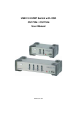
USB 2.0 KVMP Switch with OSD CS1732B / CS1734B User Manual www.aten.
CS1732B / CS1734B User Manual FCC Information This equipment has been tested and found to comply with the limits for a Class B digital device, pursuant to Part 15 of the FCC Rules. These limits are designed to provide reasonable protection against harmful interference in a residential installation. This equipment generates, uses and can radiate radio frequency energy, and if not installed and used in accordance with the instruction manual, may cause interference to radio communications.
CS1732B / CS1734B User Manual User Information Online Registration Be sure to register your product at our online support center: International North America http://support.aten.com ATEN TECH http://www.aten-usa.com/product_registration ATEN NJ http://support.aten.
CS1732B / CS1734B User Manual Package Contents The CS1732B / CS1734B USB 2.0 KVMP Switch with OSD package consists of: 1 CS1732B / CS1734B KVMP Switch 2 Custom USB KVM Cable Sets (CS1732B) 4 Custom USB KVM Cable Sets (CS1734B) 1 USB-to-PS/2 Converter 1 Firmware Upgrade Cable 1 Power Adapter 1 User Manual* 1 Quick Start Guide 2 OSD/Hotkey Stickers Check to make sure that all the components are present and that nothing got damaged in shipping.
CS1732B / CS1734B User Manual Contents FCC Information . . . . . . . . . . . . . . . . . . . . . . . . . . . . . . . . . . . . . . . . . . . . . ii RoHS. . . . . . . . . . . . . . . . . . . . . . . . . . . . . . . . . . . . . . . . . . . . . . . . . . . . . . ii SJ/T 11364-2006. . . . . . . . . . . . . . . . . . . . . . . . . . . . . . . . . . . . . . . . . . . . . ii User Information . . . . . . . . . . . . . . . . . . . . . . . . . . . . . . . . . . . . . . . . . . . . .iii Online Registration . . . . .
CS1732B / CS1734B User Manual OSD Main Screen Headings. . . . . . . . . . . . . . . . . . . . . . . . . . . . . . . . . . . 23 OSD Functions . . . . . . . . . . . . . . . . . . . . . . . . . . . . . . . . . . . . . . . . . . . . . 23 F1: KVM . . . . . . . . . . . . . . . . . . . . . . . . . . . . . . . . . . . . . . . . . . . . . . . 24 F2: USB. . . . . . . . . . . . . . . . . . . . . . . . . . . . . . . . . . . . . . . . . . . . . . . . 24 F3: AUDIO. . . . . . . . . . . . . . . . . . . . . . . . . . . . .
CS1732B / CS1734B User Manual About this Manual This User Manual is provided to help you get the most from your system. It covers all aspects of installation, configuration and operation. An overview of the information found in the manual is provided below. Introduction, introduces you to the CS1732B / CS1734B system. Its purpose, features and benefits are presented, and its front and back panel components are described.
CS1732B / CS1734B User Manual Conventions This manual uses the following conventions: Monospaced [] Indicates text that you should key in. Indicates keys you should press. For example, [Enter] means to press the Enter key. If keys need to be chorded, they appear together in the same bracket with a plus sign between them: [Ctrl+Alt]. 1. Numbered lists represent procedures with sequential steps. ♦ Bullet lists provide information, but do not involve sequential steps.
Chapter 1 Introduction Overview The CS1732B / CS1734B are two- and four-port KVMP Switches combined with a two-port USB 2.0 hub. As KVM switches, they allow users to access two and four computers from a single keyboard, monitor, and mouse console. The CS1732B / CS1734B improves on previous designs by giving the user a choice of either transferring keyboard and mouse data to the computers via a USB connection, or with the traditional PS/2 connection.
CS1732B / CS1734B User Manual Since a single console manages all of the computers, the CS1732B / CS1734B installation: 1) eliminates the expense of having to purchase separate console components for each computer; 2) saves all the space those extra components would take up; 3) saves on energy costs; and 4) eliminates the inconvenience and wasted effort involved in constantly moving from one computer to another. * For PC compatible computers.
1. Introduction Features 2/4-port KVMP switch with USB 2.0 support and 2.1 channel surround sound audio One console controls 2 (CS1732B ) or 4 (CS1734B ) computers and two additional USB devices 2-port USB 2.0 hub built in USB 2.0 compliant Dual interface – supports computers with PS/2 or USB keyboard and mouse configurations Audio-enabled – full bass response provides a rich experience for 2.
CS1732B / CS1734B User Manual Requirements Console A VGA, SVGA, or Multisync monitor capable of the highest resolution that you will be using on any computer in the installation. A USB mouse A USB keyboard Note: A PS/2 keyboard and mouse can used by using the converter included in the package Computer The following equipment must be installed on each computer: A VGA, SVGA or Multisync card. USB Type A port, or PS/2 keyboard and mouse ports.
1. Introduction Operating System Support Supported operating systems are shown in the table, below: OS Windows Linux (Kernel 2.6 and higher) UNIX Novell Version 2000 and higher RedHat 7.1 and higher; Fedora Core 2 and higher SuSE 9.0 and higher Mandriva (Mandrake) 9.0 and higher AIX 4.3 and higher FreeBSD 4.2 and higher Sun Solaris 9 and higher Netware 5.0 and higher Mac OS 9.0 and higher DOS 6.
CS1732B / CS1734B User Manual CS1732B / CS1734B Front View 1&2 USB 2.0 USB 2.0 / OSD 3 4 1&2 K/M RESET USB 2.0 USB 2.0 / OSD 3 4 (Continues on next page.
1. Introduction No. 1 Component Description Port Pressing a front panel pushbutton brings the focus to the Selection computer attached to its corresponding port. Pushbuttons There are two settings for Front Panel Pushbutton Switching Operation: MODE 1 (Default Setting) and MODE 2 (Alternative Setting). The F6:SET function in the OSD allows you choose between these two settings. See F6: SET, page 25.
CS1732B / CS1734B User Manual CS1732B / CS1734B Rear View 1 2 USB 2.0 . 3 1 4 5 2 USB 2.0 . CPU 4 3 4 CPU 3 CPU 2 CPU 1 5 (Continues on next page.
1. Introduction No. Component Description 1 Firmware Upgrade Port The Firmware Upgrade Cable that transfers the firmware upgrade data to the CS1732B / CS1734B plugs in here. See The Firmware Upgrade Utility, page 31 for details. 2 USB 2.0 USB 2.0 peripherals (printers, scanners, etc.) can plug into Peripheral Port this port. 3 Power Jack The power adapter cable plugs into this jack.
CS1732B / CS1734B User Manual This Page Intentionally Left Blank 10
Chapter 2 Hardware Setup Cable Connection 1. Important safety information regarding the placement of this device is provided on page 37. Please review it before proceeding. 2. Make sure that the power to all devices connected to the installation are turned off. You must unplug the power cords of any computers that have the Keyboard Power On function To set up your CS1732B / CS1734B installation, refer to the installation diagram on the following pages, and do the following: 1.
CS1732B / CS1734B User Manual 5. At the other end of the cable: a) For a PS/2 connection (see page 13), plug the keyboard, mouse, video, microphone and speaker cables into their respective ports on the computer. b) For a USB connection (see page 13), plug the USB, video, microphone and speaker cables into their respective ports on the computer. Repeat steps 4 and 5 for any other computers you are connecting up. 6.
2.
CS1732B / CS1734B User Manual Port Numbering Each KVM port on the CS1732B / CS1734B switch is assigned a port number (1 or 2 for the CS1732B; 1 to 4 for the CS1734B). The port numbers are marked on the rear panel of the switch (see CS1732B / CS1734B Rear View, page 8). The Port ID of a computer is derived from the KVM port number it is connected to. For example, a computer connected to KVM port 2 has a Port ID of 2.
Chapter 3 Keyboard Port Operation This chapter details the concepts and procedures involved in the keyboard port Hotkey operation of your CS1732B / CS1734B installation; hotkey operation within the OSD is discussed in the previous chapter, OSD Operation. Hotkey Port Control Hotkey Port Control allows you to provide KVM focus to a particular computer directly from the keyboard.
CS1732B / CS1734B User Manual Selecting the Active Port Each KVM port is assigned a Port ID (see Port Numbering, page 14). You can directly access any computer on the installation with a Hotkey combination that specifies the Port ID of the KVM Port that the computer is connected to. The steps involved are: 1. Invoke Hotkey Mode with the [NumLock] + [-] combination 2. Key in the Port ID 3.
3. Keyboard Port Operation Going Directly to a Port Hotkey Action [Num Lock] + [-] [Enter] Brings the KVM, USB hub, and audio focus from the port that currently has the KVM focus to the next port on the installation (1 to 2; 2 to 1 for the CS1732B; 1 to 2; 2 to 3; 3 to 4; 4 to 1 for the CS1734B). Note: The KVM, USB hub, and audio focus all go to this port even if they were on different ports to begin with.
CS1732B / CS1734B User Manual Auto Scanning Auto Scan automatically switches among all the active KVM Ports that are accessible to the currently logged on User at regular intervals, so that he can monitor their activity automatically. See the following table below for details: Hotkey [Num Lock] + [-] [A] [Enter] Action Starts Auto Scan. The KVM focus cycles from port to port at 5 second intervals. [Num Lock] + [-] [A] [n] Starts Auto Scan.
3. Keyboard Port Operation Skip Mode This feature allows you to switch between computers in order to monitor them manually. You can dwell on a particular port for as long or as little as you like – as opposed to Auto Scanning, which automatically switches after a fixed interval. To invoke Skip Mode, key in the following Hotkey combination: 1. Invoke Hotkey Mode with the [NumLock] + [-] combination 2. Key in [Arrow] Where [Arrow] refers to one of the Arrow keys.
CS1732B / CS1734B User Manual Hotkey Summary Table [Num Lock] + [-] [Enter] Brings the KVM, USB hub, and audio focus from the port that currently has the KVM focus to the next port on the installation. [Port ID] [Enter] Switches access to the computer that corresponds to that Port ID. [K] or [U] or [S] [Enter] Brings only the KVM or USB hub or audio focus from the port that currently has it to the next port on the installation.
Chapter 4 OSD Operation This chapter provides a complete description of the procedures involved in the OSD (On Screen Display) operation of your CS1732B / CS1734B installation. OSD Overview The On Screen Display (OSD) is a menu driven method to handle computer control and switching operations. All procedures start from the OSD Main Screen. To pop up the Main Screen, tap the Scroll Lock key twice. Note: You can change the Hotkey to the Ctrl key by tapping [Ctrl] twice (see OSD HOTKEY, page 25).
CS1732B / CS1734B User Manual OSD Navigation To select a port, use the F1, F2, F3 and F7 Keys or click on the Up and Down Arrow Keys to move the Highlight Bar down the list on the screen. When the Highlight Bar is on the port you want to switch to, press [Enter] or double click the left button of the mouse. The Pointing Finger icon will appear on the port selected, the OSD will disappear and the screen of the selected port will be displayed.
4. OSD Operation OSD Main Screen Headings PN This column lists the Port ID numbers for all the KVM ports on the installation. The simplest method to access a particular computer is move the Highlight Bar to its corresponding port, then press [Enter]. KVM A Pointing Finger icon in this column indicates which computer has the console focus. USB A Pointing Finger icon in this column indicates which computer has access to the USB peripheral.
CS1732B / CS1734B User Manual F1: KVM To view the screen of the KVM focus port, press [F1] or move the cursor to F1:KVM and click. Follow the steps listed under OSD Navigation, page 22). F2: USB To view the screen of the USB focus port, press [F2] or move the cursor to F2:USB and click. Follow the steps listed under OSD Navigation, page 22). F3: AUDIO To view the screen of the Audio focus port, press [F3] or move the cursor to F3:Audio and click. Follow the steps listed under OSD Navigation, page 22).
4. OSD Operation F6: SET This function allows you to set up your working environment. When you press [F6] or click on the F6 field, a screen similar to the one below appears: To change a setting: 1. Double click it; or move the Highlight Bar to it, and press [Enter]. 2. After you select an item, a submenu with further choices appears. (Press [Esc] to return to the previous menu level). To make a selection, either double click it; or move the Highlight Bar to it, and press [Enter].
CS1732B / CS1734B User Manual (Continued from previous page.) Setting BUTTON SETTINGS Function Sets the Front Panel Pushbutton Switching Operation Setting: MODE 1 (Default Setting): 1. Press a pushbutton once to bring only the KVM focus to the computer attached to its corresponding port (in 2 secs). 2. Press a pushbutton twice to bring the audio focus to the computer attached to its corresponding port (in 2 secs). 3.
4. OSD Operation (Continued from previous page.) Setting Function HOTKEY COMMAND MODE Enables / Disables the Hotkey Command function in case a conflict with programs running on the computer occurs. RESTORE DEFAULT VALUES Used to undo all the changes and return to the factory default settings (see OSD Factory Default Settings, page 40) except for the NAMES settings that were assigned to the ports, which are saved.
CS1732B / CS1734B User Manual This Page Intentionally Left Blank 28
Chapter 5 Keyboard Emulation Mac Keyboard The PC compatible (101/104 key) keyboard can emulate the functions of the Mac keyboard. The emulation mappings are listed in the table below.
CS1732B / CS1734B User Manual Sun Keyboard The PC compatible (101/104 key) keyboard can emulate the functions of the Sun keyboard when the Control key [Ctrl] is used in conjunction with other keys. The corresponding functions are shown in the table below.
Chapter 6 The Firmware Upgrade Utility The Windows-based Firmware Upgrade Utility (FWUpgrade.exe) provides a smooth, automated process for upgrading the KVM switch’s firmware. The Utility comes as part of a Firmware Upgrade Package that is specific for each device. New firmware upgrade packages are posted on our web site as new firmware revisions become available. Check the web site regularly to find the latest packages and information relating to them: http://www.aten.
CS1732B / CS1734B User Manual 4. Shut down the computers on your CS1732B / CS1734B installation. 5. Invoke Firmware Upgrade Mode (see FIRMWARE UPGRADE, page 27). The front panel LEDs flash together to indicate Firmware Upgrade Mode is in effect. Starting the Upgrade To upgrade your firmware: 1. Run the downloaded Firmware Upgrade Package file – either by double clicking the file icon, or by opening a command line and entering the full path to it.
6. The Firmware Upgrade Utility 3. Click Next to continue. The Firmware Upgrade Utility main screen appears: CS1732B/1734B [MAIN].. The Utility inspects your installation. All the devices capable of being upgraded by the package are listed in the Device List panel. 4. After you have made your device selection(s), Click Next to perform the upgrade. The firmware [Ver 1.0.] is not newer than the current firmware [Ver 1.0.
CS1732B / CS1734B User Manual If you didn’t enable Check Firmware Version, the Utility installs the upgrade files without checking whether they are a higher level, or not. As the Upgrade proceeds status messages appear in the Status Messages panel, and the progress toward completion is shown on the Progress bar. Upgrade Succeeded After the upgrade has completed, a screen appears to inform you that the procedure was successful: CS1732B/1734B [MAIN]..
6. The Firmware Upgrade Utility Upgrade Failed Shorting the Mainboard Jumper If the Upgrade Succeeded screen doesn’t appear, it means that the upgrade failed to complete successfully, in which case you should do the following: 1. Power off the CS1732B / CS1734B and remove its housing. 2. Using a jumper cap, short the jumper on the mainboard labeled J14. The diagrams indicate the jumper location on the CS1732B / CS1734B boards: CS1732B CS1734B 3. Power on the CS1732B / CS1734B.
CS1732B / CS1734B User Manual This Page Intentionally Left Blank 36
Appendix Safety Instructions General Read all of these instructions. Save them for future reference. Follow all warnings and instructions marked on the device. Do not place the device on any unstable surface (cart, stand, table, etc.). If the device falls, serious damage will result. Do not use the device near water. Do not place the device near, or over, radiators or heat registers. The device cabinet is provided with slots and openings to allow for adequate ventilation.
CS1732B / CS1734B User Manual Unplug the power cable before removing the power supply. If the system has multiple sources of power, disconnect power from the system by unplugging all power cables from the power supplies. Never push objects of any kind into or through cabinet slots. They may touch dangerous voltage points or short out parts resulting in a risk of fire or electrical shock. Do not attempt to service the device yourself. Refer all servicing to qualified service personnel.
Appendix Technical Support Technical support is available both by email and online (with a browser over the web): International Email Support Online Support support@aten.com Technical Support http://support.aten.com Troubleshooting Documentation Software Updates http://www.aten.com Telephone Support 886-2-8692-6959 North America Email Support ATEN TECH support@aten-usa.com ATEN NJ Online Support Technical Support ATEN TECH http://www.aten-usa.
CS1732B / CS1734B User Manual OSD Factory Default Settings Setting Default OSD Hotkey [Scroll Lock] [Scroll Lock] Keyboard Port Hotkey [Num Lock] + [-] Button Settings Mode 1 Port Display Duration 3 Seconds Scan Duration 5 Seconds Screen Blanker OFF (Disabled) Set Timeout OFF (Disabled) Screen Blanker Password [Enter] Screen Lock OFF (Disabled) Hotkey Command Mode ON Activate Beeper ON Port OS PC Mouse Emulation ON Language ENGLISH 40
Appendix Specifications Function Computer Connections Port Selection Connectors CS1732B CS1734B 2 4 OSD; Hotkeys; Pushbuttons Console Ports KB Video Mouse Speaker Mic. 1 x USB Type A F (Black) 1 x HDB-15 F (Blue) 1 x USB Type A F (Black) 2 x Mini Stereo Jack F (Green) 2 x Mini Stereo Jack F (Pink) KVM Ports KB 2 x SPHD-15 F (Yellow) 4 x SPHD-15 F (Yellow) Speaker 2 x Mini Stereo Jack F (Green) 4 x Mini Stereo Jack F (Green) Mic.
CS1732B / CS1734B User Manual Troubleshooting Overview Operation problems can be due to a variety of causes. The first step in solving them is to make sure that all cables are securely attached and seated completely in their sockets. In addition, updating the product’s firmware may solve problems that have been discovered and resolved since the prior version was released. If your product is not running the latest firmware version, we strongly recommend that you upgrade.
Appendix About SPHD Connectors This product uses SPHD connectors for its KVM and/or Console ports. We have specifically modified the shape of these connectors so that only KVM cables that we have designed to work with this product can be connected. Limited Warranty IN NO EVENT SHALL THE DIRECT VENDOR'S LIABILITY EXCEED THE PRICE PAID FOR THE PRODUCT FROM THE DIRECT, INDIRECT, SPECIAL, INCIDENTAL OR CONSEQUENTIAL DAMAGES RESULTING FROM THE USE OF THE PRODUCT, DISK OR ITS DOCUMENTATION.