User Manual KA9250 Read this guide thoroughly and follow the installation and operation procedures carefully in order to prevent any damage to the units and/or any devices that connect to them. This package contains: M M M M 1 KA9250 KVM Extender Module 1 Power Adapter 1 User Manual 1 Quick Start Guide If anything is damaged or missing, contact your dealer. © Copyright 2003 ATEN® International Co., Ltd. Manual Part No.
Note: This equipment has been tested and found to comply with the limits for a Class B digital device, pursuant to Part 15 of the FCC Rules. These limits are designed to provide reasonable protection against harmful interference in a residential installation. This equipment generates, uses and can radiate radio frequency energy, and if not installed and used in accordance with the instruction manual, may cause interference to radio communications.
Overview The KA9250 KVM Extender Module allows the KH0116 and KL0116 16 Port High Density KVM Switches to be operated from a remote console up to 150m away. The KA9250 module connects to the KH0116 or KL0116’s RJ-45 Remote Console port via industry standard Category 5 cable for a neat and reliable installation. When a Local and Remote Console are present, both can access the Switch.
Installation Requirements Remote Console M A VGA, SVGA, or Multisync monitor capable of the highest resolution that you will be using on any computer in the installation M A PS/2 style keyboard M A PS/2 style mouse Note: 1. If you connect a DDC type monitor to the Local unit, the monitor that connects to the Remote unit must be able to support the highest video resolution that the DDC monitor can provide. 2. You must use the same brand and model of mouse on both the local and remote units.
Rear View 1 R PO WE K LIN 9V AC C P U I/ O E T O M E R 2 3 6 4 5 1. LEDs The KA9250 has two LEDs (Power and Link) to indicate the operating status of the Local and Remote units (see p. 7, for details). 2. Mouse Port The remote PS/2 mouse plugs into this connector. 3. Keyboard Port The remote PS/2 keyboard plugs into this connector. 4. Monitor Port The remote monitor plugs into this connector. 5.
Installation All installation involves is plugging cables into their appropriate ports. Refer to the diagrams on the next page as you perform the following steps: 1. Plug the keyboard, monitor, and mouse cables for the remote console devices into their ports on the Console side of the KA9250. 2. Plug either end of the Category 5 cable into the KA9250’s Remote I/O port. Plug the other end of the cable into the Remote Console port of the KH0116 or KL0116. 3.
2 LINK PO WER 3 9V AC C P U I/ O E T O M E R 1 KH0116 2 LIN K PO WER 9V AC C P U I/ E T O M E R O 3 1 KL0116 -5- 2003-01-17
Operation The default operating environment is for both the Local and Remote consoles to be active. For security and privacy purposes, however, the Remote console can be disabled so that it cannot have access to the KH0116 / KL0116 or any of the equipment attached to it. To disable the Remote console, press the Disable Remote toggle button (KH0116), or the LCD Display toggle button (KL0116) until it clicks and locks into the In position. Now, only the Local Console has access to the Switch.
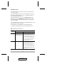
KA9250 (Remote Console): LED Indication Power 1. Lights steadily to indicate that the connection to the Local Unit is ok. 2. Flashes when there is a problem with the connection to the Local Unit. Link 1. Lights when the remote console is active. 2. Is Off when the local console is active. 3. Is Off when there is a problem with the connection to the Local Unit.
Troubleshooting Symptom No Video Action Make sure that all cables are securely plugged into their sockets. Limited Warranty IN NO EVENT SHALL THE DIRECT VENDOR’S LIABILITY EXCEED THE PRICE PAID FOR THE PRODUCT FROM DIRECT, INDIRECT, SPECIAL, INCIDENTAL, OR CONSEQUENTIAL DAMAGES RESULTING FROM THE USE OF THE PRODUCT, DISK, OR ITS DOCUMENTATION.