RS-232 To RS-485 Interface Converter IC-485S / IC-485SI User Manual Read this manual thoroughly and follow the installation procedures carefully to prevent any damage to the IC-485S / IC-485SI and/or the devices it connects to. ©Copyright 1998-2000 Aten® International Co., Ltd. Manual Part No. PAPE-1134-100 Printed in Taiwan 01/1999 All brand names and trademarks are the registered property of their respective owners.
If anything is damaged or missing, contact your dealer. Warning! This equipment generates, uses and can radiate radio frequency energy and if not installed and used in accordance with the instruction manual may cause harmful interference to radio and television reception.
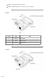
SW1 is used to select the Device Mode SW2 is used to select the Transmitting and Receiving Mode IC-485S Position SW1 1 DCE TxON, RxON 2 DTE TxRTS, RxRTS 3 Monitor TxTRS, RxON IC-485SI 3 of 10 SW2
Position SW1 SW2 1 DCE TxON, RxON 2 DTE TxRTS, RxRTS 3 X TxRTS, RxON Terminology Explanations of the SW1 and SW2 terms are given in the table below: Term Meaning DCE DCE means Data Communications Equipment; if the IC-485S / IC-485SI is going to be plugged into a DTE device, the IC-485S / IC-485SI must be set to DCE. DTE DTE means Data Terminating Equipment; if the IC-485S / IC-485SI is going to be plugged into a DCE device, the IC-485S / IC-485SI must be set to DTE.
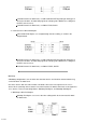
For both IC-485S / IC-485SI units, set SW1 to DCE or DTE depending on what type of device the IC-485S / IC-485SI will plug into (if it will plug into a DCE device, configure it for DTE, and vice versa). For both IC-485S / IC-485SI units, set SW2 to TxON, RxON. 2. Point-to-Point 4 Wire Half Duplex Point-to-Point Half Duplex uses straight through four wire cabling, as shown in the diagram below.
For all IC-485S / IC-485SI units, set SW1 to DCE or DTE depending on what type of device the IC-485S / IC-485SI will plug into (if it will plug into a DCE device, configure it for DTE, and vice versa). For the Master unit, set SW2 to TxON, RxON. For all Slave units, set SW2 to TxRTS, RxON. 2.
several IC-485S / IC-485SI units in a manner similar to Multidrop. The difference is that in a Simplex configuration, the Master device can only talk, and the Slave devices can only listen. Simplex uses reverse two wire cabling to link all the connected IC-485S / IC-485SI units, as shown in the figure below: For all IC-485S / IC-485SI units, set SW1 to DCE or DTE depending on what type of device the IC-485S / IC-485SI will plug into (if it will plug into a DCE device, configure it for DTE, and vice versa).
For the RS-485S: Set SW1 to Monitor. Set SW2 to TxRTS, RxON Note: 1. The RTS must be Low in Monitor Mode. 2. The R+ and R- signals are converted and linked to the RS-232 port, DB-25 pin 3. The R'+ and R'- (T+ and T-) signals are converted and linked to the RS-232 port, DB-25 pin 3. Installation 1. Set each IC-485S / IC-485SI's configuration switches according to the information provided in the Switch Configuration and Operating Modes sections. 2.
4 Receiver +V Receiver 2 +V DCE / DTE Connection Table Because of the polarity of the communication signals, a DTE configured device must connect to a DCE configured device. The shaded area in the figure below is an example of a DTE to DCE connection: Self Test To test tthe internal circit of the interface converter, connect a dumb terminal to the unit and do the following: 1. Set SW1 to DCE (if the dumb terminal is configured for DCE. 2. Set SW2 to TxON, RxON. 3.
Check that the cables are properly set up and properly connected. Check that SW1 and SW2 are set properly. Data Loss or Error Check that the Data Rate and Data Format are the same for all devices. Limited Warranty IN NO EVENT SHALL THE DIRECT VENDOR S LIABILITY EXCEED THE PRICE PAID FOR THE PRODUCT FORM DIRECT, INDIRECT, SPECIAL, INCIDENTAL, OR CONSEQUENTIAL DAMAGES RESULTING FROM THE USE OF THE PRODUCT, DISK, OR ITS DOCUMENTATION.