
User manual


8
of 10
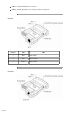
For the RS-485S:
Set SW1 to Monitor.
Set SW2 to TxRTS, RxON
Note: 1. The RTS must be Low in Monitor Mode.
2. The R+ and R- signals are converted and linked to the RS-232 port, DB-25 pin 3. The R'+
and R'- (T+ and T-) signals are converted and linked to the RS-232 port, DB-25 pin 3.
Installation
Set each IC-485S / IC-485SI's configuration switches according to the information provided in
the Switch Configuration and Operating Modes sections.
1.
Plug the IC-485S / IC-485SI's DB-25 female connector into the computer's RS-232C port.2.
Connect the IC-485S / IC-485SI units to each other:
Use two or four wire twisted pair cable in a reverse or straight through configuration
according to the information provided in the Switch Configuration and Operating Modes
sections.
For the IC-485S, you may use either the RJ-11 telephone socket, or wire directly to the
Terminal Block. (See the Terminal Block section for pin assigment details.)
For the IC-485SI, you must ground the device by connecting a grounding wire from the
Grounding Tab to the grounding source.
3.
Power on the computers. The units are now ready for operation.4.
Appendix
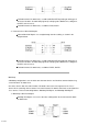
The Terminal Block
The four screw terminal block has different pin assignments depending on the operating mode:
In DCE/DTE mode, terminals 1 (+V) and 2 (-V) are configured to transmit data (the transmitter);
while terminals 3 (-V) and 4 (+V) are configured to receive data (the receiver).
In Monitor mode (IC-485S only), terminals 1 and 2 are, respectively, the positive and negative of
receiver 1; while terminals 3 and 4 are, respectively, the positive and negative of receiver 2.
Pin DCE / DTE Monitor
1 Transmitter +V Receiver 1 +V
2 Transmitter -V Receiver 1 -V
3 Receiver -V Receiver 2 -V