Temperature Controller 1/ 16 DIN - 48 x 48 M400 line c User manual • M.I.U.M400 -1/02.06 • Cod. J30-478-1AM4 SEA C UL LISTED ATHENA CONTROLS, INC. 5145 Campus Drive Plymouth Meeting PA 19462 U.S.A. Tel: (610) 828-2490 Fax: (610) 828-7084 AthenaControls.
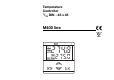
Temperature Controller 1/ 16 DIN - 48 x 48 M400 line c C UL LISTED 1 2 3 274.8 RUN SP2 MAN 275.
Information c NOTES ON ELECTRIC SAFETY AND ELECTROMAGNETIC COMPATIBILITY. Please, read carefully these instructions before proceeding with the installation of the controller. Class II instrument, rear panel mounting.
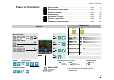
Table of contents TABLE OF CONTENTS 1 2 3 4 5 6 7 INSTALLATION .............................................................................................................................Page ELECTRICAL CONNECTIONS.......................................................................................Page PRODUCT CODING ................................................................................................................Page OPERATIONS............................................................
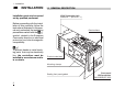
1 - Installation 1 INSTALLATION Installation must only be carried out by qualified personnel. 1.1 GENERAL DESCRIPTION IP 20 Termination Unit EN61010 - 1 (IEC1010 - 1) Before proceeding with the installation of this controller, follow the instructions illustrated in this manual and, particularly the installation precautions marked with the B symbol, related to the European Community directive on electrical protection and electromagnetic compatibility.
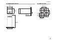
1 - Installation 1.2 DIMENSIONAL DETAILS 1.3 PANEL CUT-OUT 48 mm 1.89 in 65 mm min 2.56 in min 45+0.6 mm 1.78+0.023 in 20 mm max 0.79 in max 65 mm min 2.56 in min 48 mm 1.89 in 45+0.6 mm 1.78+0.023 in 120 mm 4.
1 - Installation B 1.
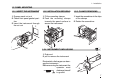
1 - Installation 1.5 PANEL MOUNTING 1.5.1 INSERT THE INSTRUMENT 1.5.2 INSTALLATION SECURING 1.5.3 CLAMPS REMOVING 1 Prepare panel cut-out 2 Check front panel gasket position 3 Insert the instrument through the cut-out 1 1 Fit the mounting clamps 2 Push the mounting clamps towards the panel surface to secure the instrument 1 Insert the screwdriver in the clips of the clamps 2 Rotate the screwdriver 1 2 1 2 3 1 2 B 1.5.
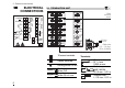
2 - Electrical connections 2 8 TC mA mV NO 3 9 C 4 10 B 5 11 b 6 12 A 15 NO 16 C 17 13 2 8 14 3 9 15 4 10 16 5 11 17 0,5 Nm Rear terminal cover 18 9 RTD 14 C 7 OP3 N 13 NO 1 TA 1 7 OP1 L B 2.1 TERMINATION UNIT OP2-R ELECTRICAL CONNECTIONS OP2-L 18V RS485 OUT (OP4) 2 11 LOGIC INPUT 6 12 5.7 mm 0.22 in 18 Cable size 0,5…1,5 mm2 (22 a 16 AWG) 18 screw terminals Terminals Option terminals Holding screw 0.
2 - Electrical connections PRECAUTIONS B Despite the fact that the instrument has been designed to work in an harsh and noisy environmental (level IV of the industrial standard IEC 801-4), it is recommended to follow the following suggestions. 2.2 PRECAUTIONS AND ADVISED CONDUCTOR COURSE B Conduit for supply and output cables B A B BB A B A All the wiring must comply with the local regulations. The supply wiring should be routed away from the power cables.
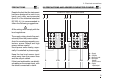
2 - Electrical connections B 2.3 EXAMPLE OF WIRING DIAGRAM (HEAT COOL CONTROL) Power supply V Supervisor ~ Retransmission Power supply [3] switch RS485 RX/TX 0P4 4…20mA Cooling ~ V Fuse [5] Fuse 0.2A T [4] 1 7 V~ Fuse [5] [6] 13 OP3 2 8 14 3 18V 9 15 OP2 OP1 4 10 16 OP2 5 11 17 6 12 18 TC CT Current transformer 50 mA ~ V Heating 10 [6] ~ Fuse 2A T ~ [6] V Alarm Notes: 1] Make sure that the power supply voltage is the same indicated on the instrument.
2 - Electrical connections 2.3.1 POWER SUPPLY B Switching power supply with multiple isolation and internal fuse • Standard version: nominal voltage: 100 - 240V~ (- 15% + 10%) Frequency 50/60Hz • Low Voltage version: Nominal voltage: 24V~ (- 25% + 12%) Frequency 50/60Hz or 24V– (- 15% + 25%) • Power consumption 2.6W max Included 0.2A T fuse L 1 Supply N 2 B 2.3.
2 - Electrical connections 2.3.2 PV CONTROL INPUT B D 2.3.3 AUXILIARY INPUT (option) For mA, mV mV mA 5 6 External Shunt 2.
2 - Electrical connections B 2.3.5 OP1 - OP2 - OP3 OUTPUTS The functionality associated to each of the OP1, OP2 and OP3 input is defined during the configuration of the instrument index l(see page 18). The suggested combinations are: Control outputs [1] A B Single output Single output C Heat/Cool D Heat/Cool E Heat/Cool OP1 - OP3 OP2 - L OP2 - R OP1 Heat OP2-L Heat OP1 Heat OP1 Heat OP2-L Heat OP2 output can be Relay (Std) or Logic.
2 - Electrical connections 2.3.5-A SINGLE OUTPUT RELAY (TRIAC) B CONTROL OUTPUT 2.3.5-C HEAT/COOL RELAY (TRIAC)/RELAY (TRIAC) CONTROL OUTPUT Fuse OP1 OP1 4 Varistor for inductive load 24V only ~ 2.3.5-B SINGLE OUTPUT LOGIC CONTROL B OUTPUT 10 Static relay Load OP2 11 Relay output • SPST Relay N.O., 2A/250 V~ for resistive load, fuse 2A ~ T Triac output • N.O.
2 - Electrical connections 2.3.6 ALARMS OUTPUTS B e The outputs OP1, OP2 and OP3, can be used as alarm outputs only if they are not configured as control outputs. B 2.3.7 OP4 ANALOGUE CONTROL OUTPUT (option) • Galvanic isolation 500V~/1 min • 0/4…20mA, (750Ω or 15V– max) 7 mA OP4 Load 8 Fuse 3 OP1 4 Coil of the load alarm contactor Fuse B 2.3.
3 - Product coding 3 PRODUCT CODING The complete code is shown on the instrument label. The informations about product coding are accessible from the front panel by mean of a particular procedure described at section 4.2.2 page 21 4 1 2 3 Instrument Label 3150 RUN SP2 MAN Hard P/N : M400-3150-0300 S/N : A0A-9909/0013 V~(L-N) : 100 ÷ 240V 50/60 Hz - 2.6W C UL LISTED 16 B C D L M N US IND. CON. EQ.
3 - Product coding 3.1 MODEL CODE The product code indicates the specific hardware configuration of the instrument, that can be modified, by specialized engineers only.
3 - Product coding 3.2 CONFIGURATION CODING The configuration code consists of 4 digits that identify the operating characteristic of the controller, as chosen by the user. Section 4.6 at page 35 reports the instructions how to set a new configuration code.
3 - Product coding A If, when the controller is powered up for the first time, the display shows the following message 4 1 2 3 9999 Conf it means that the controller has not been configured yet. The controller remain in stand-by until the configuration code is set correctly (see chapter 4.6 page 35).
4 - Operations 4 OPERATIONS 4.1.
4 - Operations 4.2 DISPLAY 4.2.1 OF THE PROCESS VARIABLES 274.8 During the operation, the parameters values cannot be modified by the user 275..0 274.8 °C Local Setpoint (manual) Operator mode 275.0 274.8 Engineering units [1] 274.8 OP1 output (auto) [2] 3150 Hard 2002 Note [1] See table page 37 [2] This display is not presented if the instrument has been configured as an On - Off controller [3] Value in Ampere.
4 - Operations 4.3 PARAMETER SETTING 4.3.1 NUMERIC ENTRY (i.e. the modification of the Setpoint value from 275.0 to 240.0 ) Operator mode Press $ or % momentarily to working Setpoint change the value of 1 unit every displayed 274.8 275.0 push Continued pressing of $ or % changes the value, at rate that doubles every second. Releasing the button the rate of change decreases. In any case the change of the value stops when it has reached the max/min limit set for the parameter.
4 - Operations 4.3.2 MNEMONIC CODES SETTING (e.g. configuration see page 35) Press the $ or % to display the next or previous mnemonic for the selected parameter. Continued pressing of $ or % will display further mnemonics at a rate of one mnemonic every 0.5 sec. The mnemonic displayed at the time the next parameter is selected, is the one stored in the parameter.
4 - Operations 4.3.3 KEYPAD LOCK 4.3.4 OUTPUTS LOCK To lock/unlock the keypad press the keys í and è simultaneously for 2 seconds. To confirm the keypad lock/unlock the display flashes once. The outputs are switched to the OFF status by pressing the keys è and %together. When the outputs are locked , the is displayed message #Off instead of the Setpoint value. To unlock the outputs press again the keys simultaneously (the Soft-start will be enabled). 274.8 operator mode 274.8 275.
4 - Operations 4.4 PARAMETERISATION 274.8 Parameter mnemonic Parameter value 275..0 35.0 Auto/Man selection (see page 24) Operator mode A.Man p.b. Values modification Prameter Modification/ menu selection selection enter A The parameter setting procedure has a timeout. If no keys are pressed for, at least, 30 seconds, the controller switches back, automatically, to the operator mode.
4 - Operations é PARAMETER MENU 33 é 0 1st GROUP Password entry [3] pAss only if Code value A2s.p AL2 alarm threshold [1] ≥5000 (see pages 35…37) 2nd GROUP tune Tuning run/stop (PID algorithm only) (see page 29) 5000 Code entry [3] from 5000 to 9999 Must be equal to the value of the parameter Code OK NO YES é 0:5 band d.bnd Dead (heat/cool configuration only) ADPT Continuous Tuning start (adaptive tuning) (PID algorithm only) PrGh p.b.
é 4 - Operations 1 é tiMe In.sé ala éL . réacnge é100:0 low limit s.p. l Setpoint low range… s.p. H Timer setting (if option installed) 1…9999 sec. or min. 0 é high limit during Op.Hs Output Start-up 0:5 F.sé éH .c réaala nge Setpoint s.p. 2 s.Stand-by p. l…s.p. H é 0 ramp up sl. u Setpoint 0ff/0.1…999.9 s.p.s.U digit/min é Off é ramp down sl. d Setpoint 0ff/0.1…999.9 digit/min hysteresis A2hy AL2 0.1…10.0% of span [1] high limit s.p. H Setpoint s.p.
4 - Operations pass Password entry [3] only if Code value <5000 (see pages 35…37) Direct access to the configuration (pages 35 … 37) [3] If password is 0000 to 4999, parameter setting will be available to the operator without entering this password number. If password is 5000 to 9999, parameter setting will only be available by entering this password number. [4] If option installed and configured for retransmission. énone A3L.b dead band d.Err Error (PID algorithm only) delay t.
4 - Operations 4.5 PARAMETERS Sensor break or input disconnection Sensor Visualisation over-range T under-range Absolute alarm On Active Off high FIRST GROUP The controller parameters have been organised in group, according to their functionality area. A # 2s.p A # 3s.
4 - Operations Overshoot control (Automatically disabled when the adaptive tuning is running). This parameter specifies the span of action of the overshoot control. Setting lower values (0.99 —> 0.01) the overshoot generated by a Setpoint change is reduced. The overshoot control doesn’t affect the effectiveness of the PID algorithm. Setting 1, the overshoot control is disabled. O # C . . Heat/Cool dead band This parameter specifies the width of the deadband between the Cool and the Heat channel. d # b .
4 - Operations L # tch ALARM ACKNOWLEDGE FUNCTION The alarm, once occurred, is presented on the display until to the time of acknowledge. The acknowledge operation consists in pressing any key. After this operation, the alarm leaves the alarm state only when the alarm condition is no longer present. b # loc ALARMS WITH LBA (LOOP BREAK ALARM) AND SENSOR BREAK OPERATION Select the code 1 on n or o configuration indexes (see pages 18 or 19). The following parameter is then available: t # L .
4 - Operations SECOND GROUP Input filter time constant Time constant, in seconds, of the RC input filter applied to the PV input. When this parameter is set to Off the filter is bypassed. t # f . il Soft-start activation time Time duration (starting from the power on) of the Soft-start function. s # t.tM Filter response 100% 63,2% PV OP 0 t.Fil I # n.
4 - Operations HEAT COOL CONTROL By a sole PID control algorithm, the controller handles two different outputs, one of these performs the Heat action, the other one the Cool action. It is possible to overlap the outputs. The dead band parameter d # b . nd, is the zone where it is possible to separate or overlap the Heat and Cool actions. The Cool action can be adjusted using the relative cool gain parameter r # C . G . a. To limit the Heat and Cool outputs the parameters 0 # p. H and 0 # p.HC can be used.
4 - Operations ANALOGUE CONTROL OUTPUT OP4 When configured, the analogue control output excludes the corresponding time proportioning control output automatically.(see page18) (e.g. if code l = 0 and # r t. h = M.U.. the OP1 is not yet available) r # etr CURRENT TRANSFORMER INPUT With CT option it is possible to display the load current and set an alarm threshold.
4 - Operations 4.6 CONFIGURATION The configuration of the controller is specified through a 4 digit code that defines the type of input, of control output and of the alarms. (sect. 3.2 page 18) Parameter value 274.8 275..0 Operator mode Auto / Man selection (see page 24) Timer run/stop (if option installed) A.Man t.run Parameter mnemonic 200.
4 - Operations CONFIGURATION MENU A2s.p entry [2] pAss Password only if Code value 1st GROUP tune 2nd GROUP ≥5000 5000 Code entry [2] from 5000 to 9999 Must be equal to the value of the parameter Direct access to the configuration Code NO OK YES Unit Engineering units (see table 1) Entry of digits I-L-M-N of the configuration code (chapter 3.2 page 18 and 19) I L M N IL.Fn Digital input function (only if installed) (see table 2) sc.d.d N° of decimals (linear scale only) 0…3 t.
4 - Operations pass 33 Password entry [2] only if Code value <5000 Code entry [2] from 0 to 4999 (33 default from factory) The entered password must correspond to the one store in the Code parameter. OK YES NO Table 1 - Supported Engineering Units. Centigrade degrees* Fahrenheit degrees * nessuna mV Volt mA Ampere Bar PSI Rh pH * A Direct access to the configuration A From parameterisation (see page 28).
5 - Automatic tuning 5 AUTOMATIC TUNING Two tuning methods are provided: • Initial one shoot Fuzzy-tuning • Continuous, self learning Adaptive Tuning The Fuzzy-Tuning allows the calculation of the optimal PID terms parameters, monitoring the response of the process to disturbances. The controller provides 2 types of “one shot” tuning algorithm, that are selected automatically according to the process condition when the operation is started.
5 - Automatic tuning The self-learning Adaptive Tuning is not intrusive. It doesn’t affect the process, at all, during the phase of calculation of the optimal terms parameters. Continuous Adaptive Tuning Perturbation New parameters It is particularly suitable for controlling process whose control characteristics change with time or are not linear in relation to the Setpoint values. It doesn’t require any operation by the user.
6 - Special functions 6 SPECIAL FUNCTIONS Two special functions are available: 6.1 Start-up 6.2 Timer In order to have the above functions the product code digit E must be 2 (see page 17) For example: M400 3100-2000 To select these functions use the parameter: Timer/Start-up operator mode (see page 36). t # M . od A Selecting Timer or Start-up, the Soft-start function is disabled, therefore the parameters #st.Op and #st.tM will not be shown. (see page 27) 6.
6 - Special functions There are two possibilities: A Start-up Setpoint # s p. s U lower than the local Setpoint. The “Hold” phase starts when the process variable PV achieves the #sp.sU (with a tolerance of 1 digit). B Start-up Setpoint #sp.sU greater than or equal to the local Setpoint. When the process variable PV achieves the local Setpoint (with a tolerance of 1 digit), the Start-up function passes directly to the “Off” phase.
6 - Special functions 6.2 TIMER FUNCTION To use AL3 in addition to this function, set the parameter C # on2 (AL3 configuration code) is set to # 0.. A The Timer can’t be enabled with Heat/Cool control. The two following parameters (see page 36) must be set to select one of the six possible types of Timer. Timer/Start-up operating mode By this parameter can be defined: - the counting start time - the control output status at the end of the counting t # M .
6 - Special functions When the timer is running it is always possible to see the remaining time and to modify it. 850 RUN 850 Operator mode and Timer running Press until 234 RUN Depending on the Timer action #t.act selection, there can be two different starting ways: - Automatic at the power on - Manual by keypad, serial communications or digital input. To start/stop the Timer: If there is a power failure during the Timer execution, the value of the elapsed time is lost.
6 - Special functions 6.2.4 TIMER COUNTING MODES A Counting start time inside the band, end in control mode. B Counting start time inside the band, end with control output forced to zero. C Counting start time = timer launch time, end in control mode. The time counting starts only when the error is inside a ± 1 digit band. The control action is not affected by the Timer function. The time counting starts only when the error is inside a ± 1 digit band. At the end, the control output is forced to zero.
6 - Special functions D Counting start time = timer launch time, end with control output forced to zero. E No control action during the counting time. F Control action with stand-by Setpoint during the counting time The time counting starts when the timer is launched. At the end, the control output is forced to zero. [1] The time counting starts when the timer is launched and the control output is forced to zero. At the end, the control action starts.
7 - Technical specification 7 TECHNICAL SPECIFICATIONS Features (at 25°C environmental temp.) Description Total configurability (see par. 3.2 page 18 par. 4.6 page 35) From keypad or serial communication the user selects: - the type of input - the associated functions and the corresponding outputs - the type of control algorithm - the type of output and the safe conditions - the type and functionality of the alarms - the values of all the control parameters.
7 - Technical specification Features (at 25°C environmental temp.
7 - Technical specification Features (at 25°C environmental temp.) Description OP1 output OP2 output OP3 output SPST Relay N.O., 2A/250V~ for resistive load Triac, 1A/250V~ for resistive load Logic not isolated: 5V–, ± 10%, 30mA max SPST Relay N.O., 2A/250V~ for resistive load SPST Relay N.O., 2A/250V~ for resistive load Triac, 1A/250V~ for resistive load OP4 countinuous control Galvanic isolation: 500 V~/1 min Resolution 12bit (0.025%) output (option) Accuracy: 0.1 % Hysteresis 0.1…10.0% c.s.
7 - Technical specification Features (at 25°C environmental temp.
1 WARRANTY We warrant that the products will be free from defects in material and workmanship for 3 years from the date of delivery. The warranty above shall not apply for any failure caused by the use of the product not in line with the instructions reported on this manual. 50 CSG srl • New Media Communications • www.csg-net.
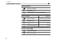
ICONS TABLE Main universal input Digital input Digital input connected functions Thermocouple Isolated contact Auto/Manual RTD (Pt100) NPN open collector Run, Hold, Reset and program selection Delta Temp (2x RTD) TTL open collector PV hold mA and mV Setpoint Custom Setpoint slopes inhibition Local Output Frequency Stand-by SPST Relay Keypad lock Triac Current transformer Outputs lock SPDT Relay mA Remote setpoint Start-up function mA Volt Remote setpoint Timer function mA mV Fee