SERIES 16C TEMPERATURE/PROCESS CONTROLLER Instruction Manual (Basic Operations) 1
Introduction Congratulations on your purchase of an Athena Series 16C Temperature/Process Controller. It is designed for ease of use and reliability wherever accurate control is required. After following the instructions for installation, simply step through and set your operating parameters using the controller’s easy menu system. The instrument may then be automatically or manually tuned to your process for optimum setpoint control.
Safety Warning In addition to presenting a potential fire hazard, high voltage and high temperature can damage equipment and cause severe injury or death. When installing or using this instrument, follow all instructions carefully and use approved safety controls. Electrical connections and wiring should be performed only by suitably trained personnel. Do not locate this instrument where it is subject to excessive shock, vibration, dirt, moisture, oil, or other liquids.
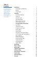
Table of Contents For information and operating instructions related to installed options and digital communications, refer to the Series C Options and Digital Communications manual supplied with your controller.
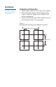
Installation Measurements between centerlines of panel cutouts are the minimum recommended. Unpacking and Inspection 1. Inspect shipping carton for obvious signs of mishandling. 2. After removing the controller from the shipping carton, inspect it carefully for damage. Never attempt to install and use a damaged unit. 3. Verify that the ordering code number indicated on the side of the controller matches what was ordered. Figure 1. Recommended Panel Layout for Multiple Controllers CL 2.850” (72.
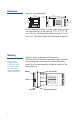
Dimensions Figure 2. Case Dimensions 2.100" (53.3mm) O1 O2 A1 2.100" A2 (53.3mm) F1 0.717" (8.21 mm) 4.654" (118.21mm) 3.937" (100 mm) PV 1.750" (44.5 mm) SV F2 Prior to mounting the Series C in your panel, make sure that the cutout opening is of the right size, 1.771” x 1.771” (45 mm x 45 mm), and deburred to enable a smooth fit. A minimum of 4” (100 mm) of depth behind the panel is required.
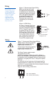
Wiring IMPORTANT: All electrical wiring connections should be made only by trained personnel, and in strict accordance with the National Electrical Code and local regulations. The Series C controller has built-in circuitry to reduce the effects of electrical noise (RFI) from various sources. However, power and signal wires should always be kept separate. We recommend separating connecting wires into bundles: power; signal; alarms; and outputs.
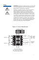
Wiring Figure 5. Thermocouple Input Wiring Make sure that you are using the appropriate thermocouple 8 and extension wire. Connect the negative lead (generally colored 9 red in ISA-type thermocouples) to contact #9; connect the 10 positive lead to contact #10. Extension wires must be the same polarity as the thermocouple. Thermocouple circuit resistance should not exceed 100 ohms for rated accuracy; errors will occur at higher resistance values.
Output Types The Type “B” output is a mechanical device and subject to wear. To extend the life of the relay, set the Cycle Time for the relay output to the longest duration that still affords good control. When you ordered your Series C controller specific output types were specified, designated as “B”, “E”, “F”, “G”, “S”, “T” or “Y”. You also had the option of configuring your controller with either one or two output actions. The numbers below are suggested for most typical applications.
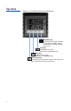
Operation Figure 9. Front Panel Controls and Indicators Mode/Enter Key Used to enter Parameter selections, access operating modes, release latched alarms, and index through menu items. Lower Key Used to decrease values. (Hold for fast-step progression) Raise Key Used to increase values. (Hold for fast-step progression) Menu Access Key Used to enter or exit the menu system, index to the next menu, and enter the Security Level menu.
Power On The Series C controller’s functional hierarchy is organized into three distinct user-programmable groupings: Security Level, Menu System, and Operating Mode. Please provide the software version number, communications protocol, and the controller’s full model number, when contacting us regarding your controller.
Security Levels The controller’s initial security level, set at the factory, is Configuration . When you have completed configuring the instrument, we recommend the security level be set to the most restrictive level suitable for your application. The security level feature allows you to limit access to the menus, setpoint, and operating mode selection according to the needs of your application. The security levels provided are Key Lockout, Setpoint, Setpoint plus Mode, User, Configuration, and Factory.
Operating Modes Remember to press the Mode/Enter key after making your selection. If both outputs are set to or , the Series C will function as a non-controlling indicator. Control outputs will be disabled and the Operating Modes will not be displayed. The Series C’s operating modes are: Manual, Standby, Normal, Autotune, Ramp/Soak Recipe, Run and Hold. To select a different operating mode, press the Mode/Enter key for three seconds. The operating mode that the controller is currently in will be displayed.
Menu System Overview If a key press is not sensed within five minutes, the controller automatically exits the Menu System and reverts to the Process Value display. The Parameter Menu System is organized into ten basic menus: Input, Display, Output, Control, Alarm, Tune, Recipe, Supervisor, Calibration, and Option. To access the Menus, press and hold the Menu Access key for approximately 3 seconds until a menu label appears in the upper display.
Menu System Overview To return to Process Value at any time, press and hold Menu Access key for three seconds for 3 seconds Figure 10.
Menu System Overview Notes: Menu Access Key Figure 11. Chart of Series 16C Menu System and Security Levels (Continued on Next Page) 1. It is recommended you start with the input menu. 2. Parameter labels displayed will vary, depending upon the controller’s configuration.
Figure 11. Chart of Series 16C Menu System and Security Levels (Continued from Previous Page) Functional When Option Card Installed Mode/ Raise/ Enter Key Lower Key (three seconds) * See options manual for parameter selections.
Menus and Parameter Descriptions Input Used to select sensor-related parameters, such as input type, limits, and scaling. Display Used to set or change decimal position and display units. Output Control Alarm Used to specify output usage, control methods, and alarms. Used to select parameters associated with the control methods. Used to select alarm parameters .
Input Menu NOTE: FOR A MORE DETAILED DESCRIPTION OF MENU PARAMETERS, REFER TO THE GLOSSARY WHICH BEGINS ON PAGE 64. The first parameter that needs to be set is Input Type. The remaining Input Menu parameters will change, depending upon whether a linear input type or a temperature input type is selected. Other menu parameters related to the sensor range may also change. After selecting your Input Type, refer to the corresponding section on page 16 for the remainder of the Input Menu parameters.
Input Menu Input Jumper Settings Input Menu (continued) Display Parameter Input Type JMPØ2 Selection 100 ohm compressed RTD 0-20 mA 4-20 mA 0-10 mV 0-50 mV 0-100 mV 10-50 mV 0-1 V 0-5 V 0-10 V 1-5 V Input Type JMPØ1 JMPØ2 Thermocouple RTD Voltage <100 mV Voltage >100 mV Current Process Out Out Out In In Out Out Out Out In Note: When you ordered your controller, an input type was specified and the controller was set up accordingly and calibrated for that input type at the factory.
Display Menu Display Parameter Decimal Position Selection 0-3 Linear Inputs 0-1 TC/RTD Filter Units* 0.1-10.0 sec Fahrenheit Celsius Kelvin *NOTE: Does not appear for linear inputs. Blanking (Time selected before setpoint diplay turns off.) Output Menu , 0-9999 sec The first parameter that needs to be set in the Output Menu is the Output Type. There are three possible Output Type configurations: PID, On/Off, Alarm, or Off.
Output Menu PID Output Type Output 1 Action Output 1 Cycle Time* Output 1 Low Limit Output 1 High Limit Output 2 Action Output 2 Cycle Time* Output 2 Low Limit Output 2 High Limit Reverse-acting (Heating) Direct-acting (Cooling) 0.2; 1 to 120 seconds 1-100% 1-100% Reverse-acting (Heating) Direct-acting (Cooling) 0.2; 1 to 120 seconds 1-100% 1-100% *Recommended Cycle Time Settings Output Type B (5A/3A) E (0-20 mA) F (4-20 mA) G (4-20 mA) S (pulsed 20 Vdc) T (S.S. relay) Y (5A/3A) N.C.
Output Menu On/Off Output Type Display Control Menu Parameter Selection Output 1 Action Reverse-acting (Heating) Direct-acting (Cooling) Output 2 Action Reverse-acting (Heating) Direct-acting (Cooling) On/Off Output Type If both outputs are set to in the Output Type Menu, the controller will function as a non-controlling indicator. Control outputs will be disabled and the Operating Modes will not be displayed.
Notes On Alarms Deviation, Inverse Band, and Normal Band Alarms track with setpoint. Outputs can be set up as an alarm, similar to the standard alarm format. Four types of alarms are available: Process, Deviation, Inverse Band, and Normal Band. All alarms may be configured to be inhibited on power-up for a configurable time duration. Process Alarm: Activates at preset value, independent of setpoint. “High” process alarm activates at and above alarm setting.
Output Menu Alarm Output Type Display Parameter Selection Output 1 Alarm Action Output 1 Alarm Operation Note: The Control Menu does not apply to an Alarm Output Type; therefore, the Control Menu does not appear. Alarms A1 & A2 can be set up using this same information in the menu.
Autotune Damping Menu Display Parameter Damping Selection Low Normal High Note: The damping parameter specifies how aggressively the controller performs its autotuning. The “Normal” setting is a compromise between the fast recovery and overshoot. The “Low” setting provides faster recovery, but with the possibility of overshoot; the “High” setting a slower recovery, but with minimum or no overshoot.
Recipe (Ramp/ Soak) Menu Power Fail Resume Setting this parameter to On will cause the control to resume a recipe which was active when a power failure occurred. The recipe will resume at the start of the last active ramp or soak segment. Ramp/Soak Events (1-8) (If alarms are configured as ramp/soak events.) Ramp/Soak events occur at the beginning of their designated segment. All events are terminated once the recipe has been completed or terminated. This can be used as an alarm when a segment is reached.
Recipe (Ramp/ Soak) Menu For Ramp Events and Soak Events to be employed, Alarm 1 or Alarm 2 must be set for event usage in the Alarm Menu. NOTE: The following seven parameters are only available when multi-step ramp is selected. Display Parameter Selection Recycle Number (Recipe Executions) 0-99, Power Fail Resume Ramp Times 1-8 Ramp Events 1-8 The Failsafe State is only enforced when a problem is detected with the process input.
Calibration Menu Toggles with the temperature value that should be input to perform the low calibration operation. The low calibration operation is triggered by pressing the up arrow key. Toggles with the temperature value that should be input to perform the high calibration operation. The high calibration operation is triggered by pressing the up arrow key.
Autotuning In order for the controller to autotune properly, the setpoint value must be at least 1% of span above or below the initial process value. Make sure that the Setpoint Target Time parameter is set to OFF. Tuning accuracy increases as the spread between ambient and setpoint value increases. Tuning should be performed with system in equilibrium (no latent energy remaining).
Autotuning If a tune error condition occurs, the upper display will toggle between and a numeric error code for three seconds before the tune process terminates. The controller will then automatically go into Standby mode when a tuning error occurs.
Manual Tuning While some processes other than heat or cool applications may respond successfully to autotuning procedures, the controller may need to be manually tuned for non-temperature processes. Manual Tuning Procedure (Zeigler-Nichols PID Method) This tuning method may be used for non-temperature control processes or if the spread between ambient temperature and process operating temperature is small. For best results, the use of a recording device is required when tuning with this method.
Error Codes Display If an error code cannot be cleared by using the actions provided, contact factory. Plus other 2-Digit Code Problem Actions Open Sensor Check sensor, wiring, and Input. Reversed Sensor Check the type selection in the Input menu, and check sensor polarity. Loop Break Correct problem and reset controller. Checksum Error RAM Error Defaults Loaded EEPROM Write Failure Press any key to perform a soft reset and reinitialize controller.
Technical Specifications Operating Limits Ambient Temperature 32°F to 140°F (0°C to 60°C) Relative Humidity Tolerance 90%, Non-Condensing Power 100 to 250 V 50/60 Hz (Single-Phase) 100 to 250 Vdc 24 Vac/dc Power Consumption Less than 6 VA Performance Accuracy Setpoint Resolution Repeatability Temperature Stability TC Cold-End Tracking Noise Rejection Process Sampling Control Characteristics Setpoint Limits Alarms Proportional Band Integral Derivative Cycle Time Control Hysteresis Autotune Manual Control ±
Technical Specifications Input Type Thermocouple RTD Linear Output Device B B, C, E, J, K, N, NIC, NNM, R, S, T, Platinel II Maximum lead resistance 100 ohms for rated accuracy Platinum 2- and 3-wire, 100 ohms at 0° C, DIN curve standard (0.00385) 1000 ohms available 0-50 mV/10-50 mV, 0-5 V/1-5 V 0-20 mA/4-20 mA, 0-100 mV, 0-10 V 5 A (120/240 Vac) relay, normally open, used for switching resistive loads. If relays or solenoids are to be driven, select the “T” output.
Ordering Codes Input Calibration Type Model 16 Output 1 Standard Options Special Options C Code CT CR CS CM CV CC CA CB Input Type Thermocouple RTD Compressed RTD Millivolt Linear Volt Linear Current Linear All TD & T/C Code 0 B E F G P S T X Output 1 None Relay (N.O.) 0 to 20 mA 4 to 20 mA High Impedance ‘F’ 20 Vdc @ 35 mA Pulsed 20 Vdc Solid-State Relay 0 to 10 Vdc Code 0 B E F G P S T Y 32 Output 2 Output 2 None Relay (N.O.
Recalibration Procedures The Series C controller is precalibrated at the factory. Under normal circumstances, the factory calibration should be valid for the life of the instrument. If recalibration should be required, allow the controller to warm up for 15 minutes and follow these steps carefully. 1) Remove power from the controller and disconnect all output devices. Disconnect input. Attach an appropriate calibrator to the input terminals.
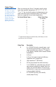
Quick-Helps 1. To return the unit to last operating mode (Normal, Standby, FOP, or Tune): Action From Menu System: Press and hold for 3 sec. From Security Level Menu: 2. To enter Standby operating mode: From Normal operating mode: From FOP (Manual) operating mode: From Menu System: Display PV + SV + Mode Press PV+ SV + Mode Action Display Press and hold for 3 sec. Press Press + PV + SV Press and hold for 3 sec. Press Press + PV + SV Press and hold for 3 sec. Press and hold for 3 sec.
Quick-Helps 5. To abort Autotuning and return to normal operation: 6. To enter FOP (Manual) operating mode: 7. To escape from FOP (Manual) operating mode: Action Press and hold for 3 sec. Press Display Press Action Press and hold for 3 sec. Press PV + SV Display + PV + % of Power Value Press to set new % of Power Value Press to + PV + set % of Power % of Power for Output 2 Value if desired. Action Display Press and hold for 3 sec.
Warranty/ Repairs Two-Year Limited Warranty THIS EQUIPMENT IS WARRANTED TO BE FREE FROM DEFECTS OF MATERIAL AND WORKMANSHIP. IT IS SOLD SUBJECT TO OUR MUTUAL AGREEMENT THAT THE LIABILITY OF ATHENA CONTROLS, INCORPORATED IS TO REPLACE OR REPAIR THIS EQUIPMENT AT ITS FACTORY, PROVIDED THAT IT IS RETURNED WITH TRANSPORTATION PREPAID WITHIN TWO (2) YEARS OF ITS PURCHASE.
Warranty/ Repairs Unit Repairs It is recommended that units requiring service be returned to an authorized service center. Before a controller is returned for service, please consult the service center nearest you. In many cases, the problem can be cleared up over the telephone. When the unit needs to be returned, the service center will ask for a detailed explanation of problems encountered and a Purchase Order to cover any charge. This information should also be put in the box with the unit.
IEC Requirements USE OF THIS EQUIPMENT IN A MANNER NOT SPECIFIED BY THE MANUFACTURER MAY IMPAIR PROTECTION PROVIDED BY THE EQUIPMENT! The maximum supply current is line voltage dependent: 230 mA for a 24 Vac/dc input 60 mA for an 85 -250 Vac input fuse rating=700 mA fuse rating=100 mA Output Specifications Output Type B T S Max current 5A 1A 20 mA Voltage 250 Vac 250 Vpk 5V Leakage 1000 M ohms 1 mA NA CLEANING INSTRUCTIONS 1. Remove power from the unit prior to any cleaning operation. 2.
Glossary Alarm Delay - the time delay between the detection of the alarm condition and the initiation and indication of the output action. Alarm Inhibit - prevents low setpoint alarm activation during cold startup applications. Bias - allows the operator to compensate for any difference between sensor temperature and the point to be measured. The process display and setpoint will be offset by the value entered in the Bias parameter in the input menu. Ex: Desired temperature is 150 degrees.
Glossary input failure, or a heater or load failure. Loop Break Time - the time interval from when the controller detects a loop break condition and the initiation of the failsafe state. Lowest Reading - records the lowest process value read by the controller. May be reset to zero by using the Raise or Lower arrow keys. Lower Setpoint Limit - prohibits users from adjusting the setpoint lower than the selected value.
Quick Setup Instructions - Series 16C Temperature Controller Experienced users, already familiar with the Series 16C, and using the controller with PID outputs, may follow these condensed instructions to autotune the controller and get started quickly once the instrument is properly mounted and wired, and the Security Level is set to . Once setup is complete, we recommend changing the Security Level back to the most restrictive level suitable for your application.
Keep This Information in a Safe Place Configured Parameters Reference Data Series C Temperature Controllers Model Number Zone Location Firmware Version No. (Displayed when the controller is powered up after all the segments on both lines of the display have been tested.) Dear Customer: Please keep this information handy – in case your controller should lose its configured initial parameter values or for easy reference when setting up a new controller.
Notes 43
For Toll-FreeTechnical Assistance in the USA, Call Toll Free: 1-800-782-6776 Athena Controls, Inc. 5145 Campus Drive Plymouth Meeting, PA 19462 U.S.A. Tel: (610) 828-2490 Fax: (610) 828-7084 Toll-Free in U.S.: 1-800-782-6776 Internet: www.athenacontrols.