Controller Indicator Transmitter 1/ 32 DIN - 48 x 24 C10 line c User manual • M.I.U.C10-1/02.06 • Cod. J30-478-1AC1 SEA C UL LISTED ATHENA CONTROLS, INC. 5145 Campus Drive Plymouth Meeting PA 19462 U.S.A. Tel: (610) 828-2490 Fax: (610) 828-7084 AthenaControls.
Controller Indicator Transmitter 1/ 32 DIN - 48 x 24 c C10 line C UL LISTED 274.
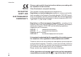
information c NOTES ON ELECTRIC SAFETY AND ELECTROMAGNETIC COMPATIBILITY. Please, read carefully these instructions before proceeding with the installation of the controller. Class II instrument, rear panel mounting.
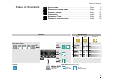
Table of contents TABLE OF CONTENTS 1 2 3 4 5 6 INSTALLATION ...........................................................................................................................Page ELECTRICAL CONNECTIONS.....................................................................................Page PRODUCT CODING ..............................................................................................................Page OPERATIONS....................................................................
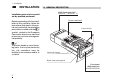
1 - Installation 1 INSTALLATION Installation must only be carried out by qualified personnel. 1.1 GENERAL DESCRIPTION IP 20 Termination Unit EN61010 - 1 (IEC1010 - 1) Product code label Before proceeding with the installation of this controller, follow the instructions illustrated in this manual and, particularly the installation precautions marked with the B symbol, related to the European Community directive on electrical protection and electromagnetic compatibility.
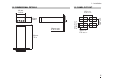
1 - Installation 1.2 DIMENSIONAL DETAILS 1.3 PANEL CUT-OUT 48 mm 1.89 in 65 mm min 2.56 in min 22.2+0.3 mm 0.87+0.01 in 20 mm max 0.79 in max 42 mm min. 1.65 in min. 25 mm 0.99 in 45+0.6 mm 1.78+0.023 in 120 mm 4.
1 - Installation B 1.
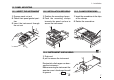
1 - Installation 1.5 PANEL MOUNTING 1.5.1 INSERT THE INSTRUMENT 1.5.2 INSTALLATION SECURING 1.5.3 CLAMPS REMOVING 1 Prepare panel cut-out 2 Check front panel gasket position 3 Insert the instrument through the cut-out 1 Position the mounting clamps 2 Push the mounting clamps towards the panel surface to secure the instrument 1 Insert the screwdriver in the clips of the clamps 2 Rotate the screwdriver 1 1 2 3 2 2 1 1 B 1.5.
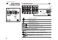
2 - Electrical connections 2 ELECTRICAL CONNECTIONS 7 8 9 +18V— OUT OP2 - L 10 11 12 5.7 mm 0.22 in 10 11 12 1 2 3 4 5 6 NO C OP1 N RTD 9 1 2 3 4 5 6 b 8 B 7 L Rear terminal cover 0,5 Nm A RS485 (OP4) B 2.1 TERMINATION UNIT Cable size 0,5…1,5 mm2 (22 a 16 AWG) TC mA 12 screw terminals mV F50- 474 1A1C1 Option terminals Holding screw 0.5 Nm Positive screw driver PH1 Negative screw driver 0,8 x 4 mm Recommended wire terminal leads Pin connector q 1.4 mm - 0.
2 - Electrical connections PRECAUTIONS B Despite the fact that the instrument has been designed to work in an harsh and noisy environmental (level IV of the industrial standard IEC 801-4), it is strongly recommended to follow the following suggestions. A All the wiring must comply with the local regulations. 2.
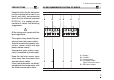
2 - Electrical connections B 2.3 TYPICAL INSTRUMENT WIRING V~ Load Solid state relays 4…20mA 0P4 Retransmission RS485 RX/TX 7 8 9 10 18V 12 OP2 Power supply switch Fuse 0.2 A T [4] Supervisory OP1 1 V~ 2 3 A 4 5 6 Pt100 B B L Supply V~ N [6] Fuse [5] V~ Coil of the load contactor 10 11 Thermocouple DC voltage Current 2.5 Ω external shunt resistor PV 2 wire transmitter Notes: 1] Make sure that the power supply voltage is the same indicated on the instrument.
2 - Electrical connections Switching power supply with multiple isolation and internal fuse • Standard version: nominal voltage: 100 - 240V~ (- 15% + 10%) Frequency 50/60Hz • Low Voltage version: Nominal voltage: 24V~ (- 25% + 12%) Frequency 50/60Hz or 24V– (- 15% + 25%) • Power consumption 1.6W max A] Single relay output • NO contact for resistive load of up to 2A / 250V~ max. • Fuse 2A~ T (IEC 127) B] Triac Output • NO contact for resistive load of up to 1A / 250V~ max. • Fuse 1A~ T (IEC 127) 0.
2 - Electrical connections B 2.3.4 PV CONTROL INPUT For L J K S T thermocouple type 5 5 6 wire resistance 150Ω max For PT100 resistance thermometer • If a 3 wires system is used, use always cables of the same diameter (1mm2 min.) (line 20 Ω/lead maximum resistance) • When using a 2 wires system, use always cables of the same diameter (1,5mm2 min.) and put a jumper between terminals 5 and 6 A When the distance between the controller and the sensor is 15 mt. using a cable of 1.
2 - Electrical connections B 2.3.5 OP4 OUTPUT (option) PV retransmission • Galvanic isolation 500V~/1 min. • 0/4...20mA, 750Ω/ 15V– max Load 7 8 mA B 2.3.
3 - Product coding 3 PRODUCT CODING The complete code is shown on the instrument label. The informations about product coding are accessible from the front panel by mean of a particular procedure described at section 4.2.2 page 19 Instrument label 3000 P/N ; C10-3000-0300 S/N : A0A-9809/0013 V~(L-N) : 100 ÷ 240V 50/60 Hz - 1.6W C UL LISTED US IND. CON. EQ.
3 - Product coding Line 3.1 MODEL CODE Model: C 10 The product code indicate the specific hardware configuration of the instrument, that can be modified by specialized engineers only. Basic A B C D - E F G H Line C 10 Power supply 100 - 240V~ (-15% + 10%) 24V~ (-25% + 12%) or 24V– (-15% + 25%) A 3 5 Output 1 [1] Relay Triac B 0 3 Option 1 Not provided RS485 Modbus/Jbus protocol Notes [1] Relay SPST N.O.
3 - Product coding 3.2 CONFIGURATION CODING The configuration code consists of 4 digits that identify the operating characteristic of the controller, as chosen by the user. Section 4.5 at pag. 26 reports the instructions how to set a new configuration code.
3 - Product coding A If, when the controller is powered up for the first time, the display shows the following message it means that the controller has not been configured yet. The controller remains in stand-by until the configuration code is set correctly (see chapter 4.6 pag 26).
4 - Operations 4 OPERATIONS 4.
4 - Operations 4.2 DISPLAY When the display operation is selected, the controller presents automatically all the most important parameters and configuration information. During the operation, the parameters values cannot be modified by the user After 2 sec from the end of the operation, the controller flashes the display and returns to the normal operating conditions. 4.2.1 OF THE PROCESS VARIABLES Operator mode 4.2.2 OF THE CONFIGURATION CODES 274.8 Operator mode after 0,5 sec.
4 - Operations 4.3 PARAMETER SETTING 4.3.1 NUMERIC ENTRY (i.e. the modification of the value of a stored Setpoint from 275.0 to 240.0) Press S or G momentarily to change the value of 1 unit every push Continued pressing of S or G changes the value, at rate that doubles every second. Releasing the button the rate of change decreases. In any case the change of the value stops when it has reached the max/min limit set for the parameter. 274.8 Operator mode 275.0 Current setpoint display —lower 230.
4 - Operations 4.3.2 MNEMONIC CODES SETTING (e.g. configuration see pages 26, 27) Press the S or G to display the next or previous mnemonic for the selected parameter. Continued pressing of S or G will display further mnemonics at a rate of one mnemonic every 0.5 sec. The mnemonic displayed at the time the next parameter is selected, is the one stored in the parameter.
4 - Operations 4.4 PARAMETER SETTING P 274.8 PASS Values modification Parameter Modification/ menù selection selection entry A The parameter setting procedure has a timeout. If no keys are pressed for, at least, 30 seconds, the controller switches back, automatically, to the operator mode. After having selected the parameter or the code, press S and G to display or modify the value (see pag. 20) The value is entered when the next parameter is selected, by pressing the R key.
4 - Operations PARAMETER MENÙ tune 2nd GROUP Tune run/stop (PID algorithm only) pass P Off sl. u Setpoint ramp up (not available with 2 alarms) 0ff/0.1…999.9 digit/min P Off Setpoint ramp down (not available with 2 alarms) 0ff/0.1…999.9 digit/min P Setpoint low limit (not available with 2 alarms) low range …s.p. H P Setpoint high limit (not available with 2 alarms) s.p. l…high range PILn.sP ala . rPacnge AL1 hysteresis 0.1…10.0% of the span [1] PF H.sP .c rPaala nge t.
4 - Operations 4.5 PARAMETER Sensor break or input disconnection Sensor 1st GROUP The controller parameters have been organized in group, according to their functionality area. AL1 alarm threshold The threshold is presented only if the controller have been configured with 2 alarms. ( Digit L of the configuration code assigned to 4 or 5) A # Is.p AL2 alarm threshold The alarm occurrences handle the OP1 and OP2 outputs, in different ways, according to the configured types of alarms, as illustrated.
4 - Operations effectiveness of the PID algorithm. Setting 1, the overshoot control is disabled. Control output high limit It specifies the maximum value the control output can be set O # p. H Control output hysteresis h # y. Setpoint low limit Low limit of the setpoint value. When the parameter is Off, this function is disabled. s # p . . l On s # p . . H A # Ihy Off hy Control output hysteresis span, set in % of the full scale.
4 - Operations CONFIGURATION MENU 4.6 CONFIGURATION Operator mode The configuration of the controller is specified through a 4 digit code that defines the type of input, of control output and of the alarms. (sect. 3.2 pag16) Other parameters specifie the type of auxiliary functions. 274.
4 - Operations 2nd GROUP tune pAss 33 Entry of digits I-L-M-N of the configuration code (chapter 3.2 page 16) YES Code entry [3] from 0 to 4999 (33 default from factory) The entered password must correspond to the one store in the Code parameter. NO [1] Table of the supported Engineering Units. Centigrade degrees * Fahrenheit degrees * none mV Volt mA I L M N 2002 OK Password entry [3] only if Code value <5000 Note Pressing the Q the next group of parameters is displayed.
5 - Automatic tune 5 AUTOMATIC TUNE Start/stop of the Fuzzy Tuning The Tuning operation can be started or stopped any time. 274.8 Operator mode press until tune stop To start select strt strt To stop select stop 28 The green led 3 goes on when the Fuzzy Tuning is in progress. At the end of this operation, the calculated PID terms parameter are stored and used by the control algorithm and the controller goes back to the operator mode. The green led 3 becomes off.
6 - Technical specification 6 TECHNICAL SPECIFICATIONS Features (at 25°C enviromental temp.) Description Total configurability see par. 3.2 pag. 16 par. 4.6 pag. 26 From keypad or serial communication the user selects: the type of input - the associated functions and the corresponding outputs - the type of control algorithm - the type of output and the safe conditions - the type and functionality of the alarms - the values of all the control parameters. Common characteristics PV Input (see pag.
6 - Technical specification Features (at 25°C enviromental temp.
6 - Technical specification Features (at 25°C enviromental temp.) Description Setpoint Ramp up and down Low limit High limit OP4 PV retransmission (option) One shot Fuzzy-Tuning with automatic selection Serial comm. (option) Auxiliary Supply Galvanic isolation: 500 V~/1 min Current output: 0/4…20mA 750Ω/15V max Resolution 12bit (0.025%) Accuracy: 0.
1 WARRANTY We warrant that the products will be free from defects in material and workmanship for 3 years from the date of delivery. The warranty above shall not apply for any failure caused by the use of the product not in line with the instructions reported on this manual. 32 CSG srl • New Media Communications • www.csg-net.
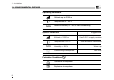
ICONS TABLE Main universal input Digital input Digital input connected functions Thermocouple Isolated contact Auto/Manual RTD (Pt100) NPN open collector Run, Hold, Reset and program selection Delta Temp (2x RTD) TTL open collector PV hold mA and mV Setpoint Custom Setpoint slopes inhibition Local Output Stand-by SPST Relay Keypad lock Triac Current transformer Outputs lock SPDT Relay mA Remote setpoint Start-up function mA Volt Remote setpoint Timer function mA mV Feedback potent