Protector ™ U.S. Patent Nos. 6069415 and 6690208 Robotic Collision Sensor SR-61, 81, 101, 131, 176, and 221 Installation Instructions for Coolant Protection Boot Document #9610-60-1008-04 November 2007 Engineered Products for Robotic Productivity Pinnacle Park • 1031 Goodworth Drive • Apex, NC 27539 • Tel: 919.772.0115 • Fax: 919.772.8259 • www.ati-ia.com • Email: info@ati-ia.
Protector Installation & Operation Manual Document #9610-60-1008-04 ! CAUTION: This manual describes the function, application and safety considerations of this product. This manual must be read and understood before any attempt is made to install or operate the product, otherwise damage to the product or unsafe conditions may occur. Information contained in this document is the property of ATI Industrial Automation, Inc.
Protector Installation & Operation Manual Document #9610-60-1008-04 Table of Contents Page 1. Installation of Coolant Protection Boot...................................................................... 5 1.1 Attach Interface Plate to Robot .......................................................................... 5 1.2 Attach the Collision Protection Device (CPD) to the Robot Interface Plate........ 5 1.3 Attach the Stem Side Interface Plate to the Stem of the CPD ........................... 6 1.
Protector Installation & Operation Manual Document #9610-60-1008-04 Glossary of Terms Term Definition Body Cylindrical aluminum housing and air pressure chamber. An interface plate to the user’s robot is usually attached here. Collision The accidental impact between the end of arm tooling and some obstruction in its path. Cover Plate Disk-shaped aluminum cover for Protector™ Body. Crash The result of a disturbance that displaces the Protector™ components from their standard, working position.
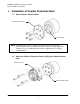
Protector Installation & Operation Manual Document #9610-60-1008-04 1. Installation of Coolant Protection Boot 1.1 Attach Interface Plate to Robot Robot Interface Plate Robot Flange NOTE: A Robot Interface Plate is required. The Robot Interface Plate can be purchased from ATI or manufactured by the customer using ATI approved drawings. The use of Robot Interface Plates supplied by ATI is strongly recommended. 1.
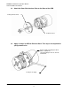
Protector Installation & Operation Manual Document #9610-60-1008-04 1.3 Attach the Stem Side Interface Plate to the Stem of the CPD Tooling Interface Plate Collision Sensor 1.4 Apply 10–20 psi to CPD to Raise the Stem. This step is not required for spring-loaded units. #10-32 or M5 x 0.8 Fitting for SR-61, SR-81, and SR-101. 1/8” NPT Fitting for SR-131, SR-176, and SR-221. 10–20 psi air supply Pinnacle Park • 1031 Goodworth Drive • Apex, NC 27539 • Tel: 919.772.0115 • Fax: 919.772.8259 • www.ati-ia.
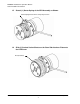
Protector Installation & Operation Manual Document #9610-60-1008-04 1.5 Stretch (1) Garter Spring of the CPD Assembly as Shown Garter Spring Stretched into Temporary Position 1.6 Slide (1) Coolant Sealant Boot over the Stem Side Interface Plate onto the CPD Cover Boot (installed) Pinnacle Park • 1031 Goodworth Drive • Apex, NC 27539 • Tel: 919.772.0115 • Fax: 919.772.8259 • www.ati-ia.com • Email: info@ati-ia.
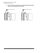
Protector Installation & Operation Manual Document #9610-60-1008-04 1.7 Secure the Coolant Sealant Boot to the CPD by Positioning the Garter Springs in the Spring Grooves on the Boot Spring Grooves in Boot Garter Springs (installed) Pinnacle Park • 1031 Goodworth Drive • Apex, NC 27539 • Tel: 919.772.0115 • Fax: 919.772.8259 • www.ati-ia.com • Email: info@ati-ia.
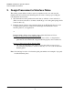
Protector Installation & Operation Manual Document #9610-60-1008-04 2. Design/Procurement of Interface Plates This sealing system utilizes a bellows style boot attached to the cover and stem side interface plate and a molded wire channel gasket. In order to insure proper sealing the following items are necessary: 1) The unit must have been purchased from the factory with the coolant sealant boot. (This is necessary since the cover must contain the groove for the garter spring and be sealed to the body.
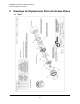
Protector Installation & Operation Manual Document #9610-60-1008-04 3. Drawings for Replacement Parts & Interface Plates 3.1 SR-61 Pinnacle Park • 1031 Goodworth Drive • Apex, NC 27539 • Tel: 919.772.0115 • Fax: 919.772.8259 • www.ati-ia.com • Email: info@ati-ia.
Protector Installation & Operation Manual Document #9610-60-1008-04 Pinnacle Park • 1031 Goodworth Drive • Apex, NC 27539 • Tel: 919.772.0115 • Fax: 919.772.8259 • www.ati-ia.com • Email: info@ati-ia.
Protector Installation & Operation Manual Document #9610-60-1008-04 3.2 SR-81 Pinnacle Park • 1031 Goodworth Drive • Apex, NC 27539 • Tel: 919.772.0115 • Fax: 919.772.8259 • www.ati-ia.com • Email: info@ati-ia.
Protector Installation & Operation Manual Document #9610-60-1008-04 Pinnacle Park • 1031 Goodworth Drive • Apex, NC 27539 • Tel: 919.772.0115 • Fax: 919.772.8259 • www.ati-ia.com • Email: info@ati-ia.
Protector Installation & Operation Manual Document #9610-60-1008-04 3.3 SR-101 Pinnacle Park • 1031 Goodworth Drive • Apex, NC 27539 • Tel: 919.772.0115 • Fax: 919.772.8259 • www.ati-ia.com • Email: info@ati-ia.
Protector Installation & Operation Manual Document #9610-60-1008-04 Pinnacle Park • 1031 Goodworth Drive • Apex, NC 27539 • Tel: 919.772.0115 • Fax: 919.772.8259 • www.ati-ia.com • Email: info@ati-ia.
Protector Installation & Operation Manual Document #9610-60-1008-04 3.4 SR-131 Pinnacle Park • 1031 Goodworth Drive • Apex, NC 27539 • Tel: 919.772.0115 • Fax: 919.772.8259 • www.ati-ia.com • Email: info@ati-ia.
Protector Installation & Operation Manual Document #9610-60-1008-04 Pinnacle Park • 1031 Goodworth Drive • Apex, NC 27539 • Tel: 919.772.0115 • Fax: 919.772.8259 • www.ati-ia.com • Email: info@ati-ia.
Protector Installation & Operation Manual Document #9610-60-1008-04 3.5 SR-176 Pinnacle Park • 1031 Goodworth Drive • Apex, NC 27539 • Tel: 919.772.0115 • Fax: 919.772.8259 • www.ati-ia.com • Email: info@ati-ia.
Protector Installation & Operation Manual Document #9610-60-1008-04 Pinnacle Park • 1031 Goodworth Drive • Apex, NC 27539 • Tel: 919.772.0115 • Fax: 919.772.8259 • www.ati-ia.com • Email: info@ati-ia.
Protector Installation & Operation Manual Document #9610-60-1008-04 3.6 SR-221 Pinnacle Park • 1031 Goodworth Drive • Apex, NC 27539 • Tel: 919.772.0115 • Fax: 919.772.8259 • www.ati-ia.com • Email: info@ati-ia.
Protector Installation & Operation Manual Document #9610-60-1008-04 Pinnacle Park • 1031 Goodworth Drive • Apex, NC 27539 • Tel: 919.772.0115 • Fax: 919.772.8259 • www.ati-ia.com • Email: info@ati-ia.
Protector Installation & Operation Manual Document #9610-60-1008-04 4. Terms and Conditions of Sale The following Terms and Conditions are a supplement to and include a portion of ATI’s Standard Terms and Conditions, which are on file at ATI and available upon request. ATI warrants to Purchaser that Protector™ products purchased hereunder will be free from defects in material and workmanship under normal use for a period of one (1) years from the date of shipment.