
Specs

GENERATOR START CONTROL MODULE - MINI (2 Wire to 3 Wire) GSCM-MINI-D
ATKINSON ELECTRONICS, INC. REV 07/08
Web Site: www.atkinsonelectronics.com Distributed by:
GENERATOR EMERGENCY SHUTDOWN WITH THE GSCM-mini-D SECTION - 7
The GSCM-mini-D Generator Start Stop module is NOT AN EMERGENCY SHUTDOWN DEVICE!! If the manual start signal is
removed the generator will go through a normal shutdown which may take up to 15 seconds to completely shutdown the generator.
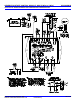
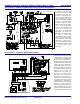
A RECOMMENDED EMERGENCY SHUTDOWN SOLUTION is to install a separate “Kill” switch and label it as such. The
recommended wiring is shown on page-2 of these instructions and also in Application 1. Disconnecting the power to the GSCM-mini-D
module will force the relays to open. This will shutdown generators that require a maintained run signal from K1 relay. However this
also prevents the K2 relay from closing to shutdown those generators requiring a momentary stop signal. Using a double pole “Kill”
switch and wiring the second pole in parallel with the K2 relay terminals will force the generator to stop in an emergency situation such
as a fuel spill. (see note 1 on wiring diagram, page 2, for Ignition/crank emergency shutdown option).
LED DESCRIPTION (WHAT THEY MEAN) SECTION - 8
1. Start: one blink every 5 seconds = Ready mode, looking for a start signal;
one blink every 2.5 seconds = auto start mode operation;
one blink every other second= auto start/stop period,
continuous = manual start signal received;
fast blink = 60 second delay after start signal removed before generator started;
2. Generator Hz fast blink = over speed condition;
Shutdown: slow blink = under speed condition;
double blink = Maximum Crank attempts reached, Failed to Start;
triple blink = Auto start attempted with-in 30 minutes of a Max run time (6 hour ) shutdown;
Four blinks every 2 seconds = Ac Hz or 12v run status signal lost during run mode;
continuous = start function disabled, AC Hz detected while in ready mode;
3. Run: continuous = GSCM has a valid run signal from generator;
4. Fault: continuous = GSCM is in a fault condition and requires a reset;
5. K1 & K2: continuous = Status of K1 and K2 Relays “ON”
SPECIFICATIONS SECTION - 9
SIZE & WEIGHT: 5.13" L x 2.853" W x 1.35" H, 20oz.
MOUNTING: 2 screws through tabs
POWER: 12VDC Battery (9.5 to 15VDC)
Quiescent current < 10mA
Relay current < 25mA ea.
MANUAL INPUT: B+ (12VDC) input = on condition
Open input = off condition
BATTERY INPUT: 0-60V DC
AUTO START/ Start Stop
STOP THRESHOLD: 12V System 11.5V, 13.8V
24V System 23.0V, 27.6V
48V System 46.0V, 55.2V
RELAY CONFIG.: Open input = Momentary Crank
(Terminal 6) Grounded input = Maintained Crank
B+ (12VDC) input = Ignition & Crank
Gen. Hz Enable: Open input = Gen. Hz shutdown not active
(Terminal 8) Grounded input = Gen. Hz shutdown active
12VDC input = Generator run Status input,
Over/Under Hz shutdown not active
FREQUENCY INPUT: 24VAC, 120VAC & 240VAC 0-100 Hz
(Terminals 9 & 10)
OUTPUT RATINGS: Qty. (2) 10 Amp 28V DC relay
contacts, K1 has 38vdc MOV
across contact
Qty. (2) Open collector NPN
transistors, Max. 300mA each
FAULT DETECTION: Start Failure, (3 attempts)
Over Hz condition (10 seconds)
Under Hz condition (10 seconds)
Max Run time (6 hours)
Loss of AC Hz or 12V run status
signal
AMBIENT TEMP: -40 to 858C