High Performance Powered Subwoofers 444 SB 334 SB 224 SB Instruction Manual Model 224 SB Model 334 SB Model 444 SB
Safety Precautions Model 224, 334 and 444 SB Powered Subwoofer Safety Precautions Table of Contents 2 3 4 5 CAUTION: To reduce the risk of electric shock, do not remove the cover (or back). No user serviceable parts inside. Refer to qualified personnel. WARNING: To reduce the risk of fire or electric shock, do not expose this appliance to rain or moisture. This device generates a fair amount of heat. Make sure nothing blocks the ventilation openings on the top and bottom of the unit.
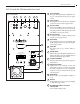
Subwoofer Rear Panel Instruction Manual 3 224, 334 and 444 SB Subwoofer Rear Panel 1 Figure 1 - 224 SB shown 1 2 3 4 5 6 The outputs allow daisy chaining of multiple subwoofers, or as a return path back to the processor. (pages 4 and 5) 7 2 OUTPUT LOW-PASS INPUT 60 L/MONO BYPASS 40 STATUS NORMAL ON 160 INVERT AUTO Low Level Input Use the input to connect to the subwoofer or LFE line out from your processor/receiver.
Features Model 224, 334 and 444 SB Powered Subwoofer Clear Filter™ Technology and Other Features Your Atlantic Technology powered subwoofer has been engineered using the latest technology and finest components available. It features: Exclusive – Atlantic's Clear Filter Technology Clear Filter Technology™ is an exclusive Atlantic design feature that ensures the cleanest, most articulate bass possible from a subwoofer.
0 0 nd ng CTRIC SHOCK. MOISTURE. PAS OUVRIR ISK OF FIRE, ING OF FUSE VICING, T PARTS 100 NORMAL ON Connecting Your Subwoofer 160 INVERT Instruction ManualAUTO Connecting Your Subwoofer Use the low-level (RCA jack) subwoofer line out of your surround sound receiver/processor. Simply connect your subwoofer with a high quality shielded cable as shown in the diagram on page 7. Please consult your processor/receiver manual for further information.
Low Level Connections Model 224, 334 and 444 SB Powered Subwoofer Low Level Connections with One Subout/LFE Output Figure 3 Sub Out/LFE OUTPUT L/MONO RIGHT INPUT
Low Level Connections Instruction Manual Low Level Connections with Two Subout/LFE Outputs Figure 4 Sub Out/LFE Sub Out/LFE OUTPUT L/MONO RIGHT INPUT 7
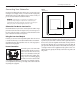
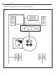
Placement and Operation Model 224, 334 and 444 SB Powered Subwoofer Placement and Operation Generally speaking, the best location for your new subwoofer is the front of the room, close to a corner (Figure 5). Every room has its own unique sound characteristics, and flexibility in the exact placement of the subwoofer is always desirable. The closer the subwoofer is placed to a wall and especially a corner, the more and deeper the bass response you will hear.
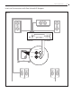
Care of your Subwoofer Instruction Manual 9 The Phase Invert Control Dual Subwoofer Placement When two subwoofers are used, you may wish to place them asymmetriLOW-PASS INPUT positions in the room (Figure cally; that is, OUTPUT in slightly different 7). This will reduce common mode room resonances that occur60 with symmetri-100 cally positioned subwoofers. You can also try placing the subwoofers in L/MONO the same corner, if you wish.
Troubleshooting Model 224, 334 and 444 SB Powered Subwoofer Subwoofer Troubleshooting Guide Once your subwoofer is set up, you should have many years of maintenance free enjoyment from your system. However, if you should encounter a problem, refer to the following guide to help you find the solution. If a problem persists, you should contact your local authorized Atlantic Technology dealer.
Instruction Manual Notes 11
343 Vanderbilt Avenue Norwood, MA 02062 (781) 762-6300 www.atlantictechnology.