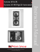
System 10 LCR System 10 SR Dipole Surround System 10 InWall Speakers Instruction Manual ● ● ● ● ● ● ● ● ● ● ● 1 ● ● ● ● ● ● ● ● ● ● ● 343 Vanderbilt Ave. Norwood, MA 02062 (781) 762-6300 www.atlantictechnology.
System 10 InWall Speakers Thank you for purchasing Atlantic Technology products. Our speaker systems have been designed to deliver exceptional sound and value. We hope you like what you hear from them, and are happy with your decision to buy them. Please take a few moments to read these instructions. They’re intended not only to tell you how to mount the speakers, but how to get the best performance from them.
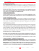
System 10 InWall Speakers Home Theater Locations of Choice Left/Center/Right Locations The front three speakers should be at ear height when seated, just as with as stereo speakers. Unfortunately, the presence of the television tends to make this difficult, if not impossible to achieve. (Unless you’re using a front projector and a perforated screen with the center channel speaker directly behind it). The closer you can get to this ideal the better, however.
System 10 InWall Speakers Mounting Issues System 10 LCR We always recommend a professional be involved in the installation of InWall Theater System speakers, if at all possible. The System 10 LCR speaker can be easily mounted in most any standard wall material, from 1/2 to 1 1/2 inches (12 to 38 mm) thick. Its rotating wall clamps firmly fix it to the wall surface after the proper cutout has been made.
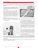
System 10 InWall Speakers Installing the Mounting Frame The clamping mechanism allows the wall material to range from 1/2 to 1 1/2 inches (12 to 38 mm) in thickness. There must be a minimum depth behind the wall face of 3 5/8” (92 mm). As noted above, be sure to keep the edges of the cutout at least 1 inch (25 mm) away from any stud or obstruction, as the rotating clamps will not operate properly if you don’t.
System 10 InWall Speakers There must be a minimum depth behind the wall face of 3 5/8 (92 mm). Be sure to keep the edges of the cutout at least 1 inch (25 mm) away from any stud or obstruction. The speaker assembly itself (the part with the drivers mounted in it, the trimming bezel, etc.) is designed to mount to the Installation Bracket after it has been installed within the wall. Step 1.
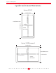
System 10 InWall Speakers Speaker and Cutout Dimensions System 10 LCR 15 13/16 inches ○ ○ ○ ○ ○ ○ ○ ○ ○ ○ ○ ○ ○ 8 13/16 inches ○7 ○ inches ○ ○ ○ ○ ○ ○ ○ ○ ○ ○ ○ ○ ○ ○ ○ ○ ○ ○ ○ ○ ○ ○ ○ ○ ○ ○ 17 1/4 inches OutsideDimensions Cutout Dimensions System 10 SR Surround 11 inches ○ ○ ○ ○ ○ ○ ○ ○ ○ ○ ○ ○ ○ ○ ○ ○ ○ ○ 15 5/8 inches OutsideDimensions ○ ○ ○ ○ ○ ○ ○ ○ ○ ○ ○ ○ ○ ○ ○ ○ ○ ○ ○ ○ ○ ○ ○ ○ ○ ○ ○ ○ ○ 14 3/8 inches ● ● ● ● ● ● ● ● ● ● ● 12 1/16 inches Cutout Dimensions 7 ● ● ● ● ● ● ● ● ● ● ●
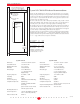
System 10 InWall Speakers Proportions illustrated are for 16" on-center 2" X 4" stud installation. See table below for proper dimensions. System 10 LCR InWall Enclosure Recommendations Toe nail or screw to hold firebock in position until sealant dries. Please use this information to construct an in-wall enclosure if you so desire. Doing so will generally improve the performance and increase the power handling of the system.