
Fast Ethernet Switch Layer 2 User's Guide


9
I
DENTIFYING
E
XTERNAL
C
OMPONENTS
This section identifies all the major external components of the
switch.
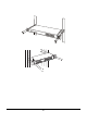
Front Panel
The figure below shows the front panels of the switch.
Power
13 14 15 16
5
1
9
62
10
73
11
84
12
1 2 3 4 5 6 7 8 9 10 11 1 2 13 14 15 16
LINK
100Mbps
16 and 24 -port 10/100Mbps Fast Ethernet Switch
LED Indicator Panel
Refer to the detailed information about each of the switch’s LED
indicators.
Power (PWR)
This indicator lights green when the switch is receiving power,
otherwise, it is off.