Atlas Copco OSC 145 AIF999999 Instruction book
Atlas Copco OSC 145 AIF999999 Instruction book Original instructions Copyright notice Any unauthorized use or copying of the contents or any part thereof is prohibited. This applies in particular to trademarks, model denominations, part numbers and drawings. This instruction book is valid for CE as well as non-CE labelled machines. It meets the requirements for instructions specified by the applicable European directives as identified in the Declaration of Conformity. 2012 - 11 www.atlascopco.
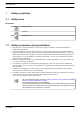
Instruction book Table of contents 1 Safety precautions..........................................................................................................3 1.1 SAFETY ICONS...................................................................................................................................3 1.2 SAFETY PRECAUTIONS DURING INSTALLATION...........................................................................................3 1.3 SAFETY PRECAUTIONS DURING OPERATION..................
Instruction book 1 Safety precautions 1.1 Safety icons Explanation Danger for life Warning Important note 1.2 Safety precautions during installation 1. Place the device where the ambient air is cool and as clean as possible. Consult section Reference conditions and limitations. 2. During installation or any other intervention on one of the connected machines, the machines must be stopped, de-energized and the isolating switch opened and locked before any maintenance or repair.
Instruction book 1.3 Safety precautions during operation All responsibility for any damage or injury resulting from neglecting these precautions, or non-observance of the normal caution and care required for installation, operation, maintenance and repair, even if not expressly stated, will be disclaimed by the manufacturer. 1. Persons switching on remotely controlled machines shall take adequate precautions to ensure that there is no one checking or working on the machine.
Instruction book 8. All regulating and safety devices shall be maintained with due care to ensure that they function properly. They may not be put out of action. 9. Before clearing the device for use after maintenance or repair, check that operating pressures, temperatures and time settings are correct. Check that all control and shut-down devices are fitted and that they function correctly. 10. Make sure that no tools, loose parts or rags are left in or on the device. 11.
Instruction book 2 General description 2.1 Introduction Compressed air produced by oil-injected compressors contains a small quantity of oil. During the cooling of the air in the aftercooler and in the refrigeration dryer (on compressors with built-in refrigeration dryer), oilcontaining condensate is formed. OSC are condensate treatment devices, designed to separate the major part of this oil from the condensate and absorb it in filters.
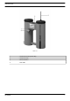
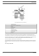
Instruction book OSC 145 1 Condensate outlet (at rear side) 2 Condensate inlet 3 Service indicator 4 Test outlet AIF999999 7
Instruction book Flow diagram (OSC 35 up to OSC 145) 1 Condensate inlet 2 Service indicator (oleophilic filter) 3 Mufflers 4 Oleophilic filter 5 First tower 6 Condensate outlet 7 Activated carbon filter 8 Second tower 9 Protector The condensate, containing fine oil droplets, enters the unit via mufflers (3) and is depressurised. The condensate flows to the first tower and seeps through an oleophilic filter (4), which absorbs most of the oil.
Instruction book OSC 355 1 Condensate outlet (at rear side) 2 Service indicator (unit clogged) 3 Condensate inlet 4 Service indicator (oleophilic filter) 5 Mufflers 6 Oleophilic filters 7 Activated carbon filters 8 First tower 9 Second tower 10 Third tower 11 Test outlet 12 Diffuser The condensate, containing fine oil droplets, enters the unit via mufflers (5) and is depressurised.
Instruction book The water from the first tower, still containing a small quantity of oil, gradually flows to a second tower (9), where two filters are fitted: a small oleophilic filter, which absorbs some more oil from the condensate, and an activated carbon filter (7). The activated carbon filter starts to absorb the remaining oil in the condensate. The condensate gradually flows to a third tower (10), where another activated carbon filter is fitted, which absorbs almost all of the remaining oil.
Instruction book 3 Installation 3.
Instruction book 3.
Instruction book Reference Description 4 Condensate outlet 5 Tower 1 6 Tower 3 7 Tower 2 8 Diffuser 9 Condensate outlet (test) 10 Protector A Housing part 1 B Housing part 2 Procedure 1. Install the OSC on a level floor, suitable for taking its weight. Keep in mind to reserve sufficient free space for replacement of the filters (see section Maintenance). 2. On OSC 355 and OSC 600: If the three towers stand in one line, rotate the third tower to the front.
Instruction book 4 Operating instructions 4.1 Putting into operation (commissioning) • The plastic bag of the filters must be removed. Do not remove the net around the filters. • The activated carbon filter in the second tower must be placed on the flow plate. • On OSC 355 and OSC 600, do not remove the flow plate. On all other models, the flow plate is not removable. Check that the activated carbon filters do not float. If necessary, hold them submerged until they remain down.
Instruction book 5 Maintenance 5.1 Maintenance Check the filters regularly as explained below in order to prevent untreated condensate from entering the sewer. Sample the condensate weekly. • If the filters are not installed properly, oil-containing condensate can leave the OSC. • When new activated carbon filters are placed, the outgoing water may initially look black (caused by carbon dust). This is not harmful. • Each new filter is provided with a label. The correct position is marked on the label.
Instruction book The filter must be replaced when the service indicator (see section Introduction) approaches the lid of the tower. The lifetime of the filter depends on the amount of oil in the condensate. Replacement instructions 1. Stop the compressor and close the air outlet valve. Switch off the voltage. Depressurise the outlet piping by opening the manual condensate drain. 2. Remove the lid of the first tower and take out the oleophilic filter (4 - Flow diagram of OSC 35 up to OSC 145).
Instruction book 5.2 Service kits Atlas Copco has a complete range of service kits available. Service kits comprise all parts needed for servicing components and offer the benefits of using genuine Atlas Copco parts while keeping the maintenance budget low. Service kits 1 Activated carbon filters 2 Oleophilic filters 3 Diffuser 4 Mufflers For each type of OSC, three service kits are available: • Service kit A comprises the material to change the oleophilic filter(s) once.
Instruction book Part Number Service kit A 2901 1401 00 Service kit B 2901 1401 01 Service kit D 2901 1576 00 OSC 145 Part Number Service kit A 2901 1402 00 Service kit B 2901 1402 01 Service kit D 2901 1577 00 The service kits for OSC 35 up to OSC 145 comprise: Quantity, service kit A Quantity, service kit B Quantity, service kit D Oleophilic filter 1 2 1 Activated carbon filter 0 1 1 Diffuser 1 2 1 Mufflers 1 2 1 Part Number Service kit A 2901 1403 00 Service kit B 2901 1
Instruction book Quantity, service kit A Quantity, service kit B Quantity, service kit D Oleophilic filter 1 2 1 Small oleophilic filter 1 2 1 Activated carbon filter 0 2 2 Diffuser 1 2 1 Mufflers 1 2 1 Part Number Service kit A 2901 1410 00 Service kit B 2901 1410 01 Service kit D 2901 1583 00 The service kits for OSC 2400 comprise: Quantity, service kit A Quantity, service kit B Quantity, service kit D 5.
Instruction book Parts OSC 95 Part Number Lid of the first tower, indicator and protector (5-Flow diagram of OSC 35-145) 1622 2935 80 Lid of the second tower (8-Flow diagram of OSC 35-145) 1622 2936 00 Ball valve (for test outlet) 0852 0010 70 Reference glass 1622 6213 00 Parts OSC 145 Part Number Lid of the first tower, indicator and protector (5-Flow diagram of OSC 35-145) 1622 2935 80 Lid of the second tower (8-Flow diagram of OSC 35-145) 1622 2936 00 Ball valve (for test outlet) 0852 0
Instruction book Parts OSC 1200 Part Number Lid of the first tower, indicator and protector (8-View of OSC 355) 1622 2999 80 Lid of the second tower (9-View of OSC 355) 1622 2999 81 Lid of the third tower (10-View of OSC 355) 1622 3009 00 Flexible between first and second tower 1622 2953 02 Ball valve (for test outlet) 0852 0010 70 Reference glass 1622 6213 00 Parts OSC 2400 Part Number Lid of the first tower, indicator and protector (8-View of OSC 355) 1622 2999 80 5.
Instruction book 6 Problem solving Condition Fault A lot of oil entered the Compressor OSC. malfunctioning The service indicator (3 - View of OSC 52) rises Replace all filters. Clean the vessels. Check the compressor. Too much condensate Check the compressor FAD (see section Technical data). flows into the OSC. The unit is clogged. 22 Remedy Replace the activated carbon filters. Check the flexible between the first and the second tower.
Instruction book 7 Technical data 7.
Instruction book Models OSC 145 Cold climate l/s 105 280 415 1035 1800 2410 3450 6895 Mild climate l/s 45 118 175 435 760 1020 1455 2910 Hot climate l/s 20 50 75 190 330 440 630 1260 Correction factors For operation in other than reference conditions, multiply the compressor capacity (FAD) with the appropriate correction factors. Running hours per day 8 10 12 14 16 18 20 22 24 Correction factor 1.50 1.20 1.00 0.86 0.75 0.67 0.60 0.55 0.
In order to be First in Mind—First in Choice® for all your quality compressed air needs, Atlas Copco delivers the products and services that help to increase your business’ efficiency and profitability. Atlas Copco's pursuit of innovation never ceases, driven by our need for reliability and efficiency. Always working with you, we are committed to providing you the customized quality air solution that is the driving force behind your business. www.atlascopco.