
Product Manual

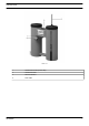
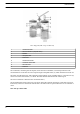

Flow diagram (OSC 35 up to OSC 145)
1 Condensate inlet
2 Service indicator (oleophilic filter)
3 Mufflers
4 Oleophilic filter
5 First tower
6 Condensate outlet
7 Activated carbon filter
8 Second tower
9 Protector
The condensate, containing fine oil droplets, enters the unit via mufflers (3) and is depressurised. The
condensate flows to the first tower and seeps through an oleophilic filter (4), which absorbs most of the oil.
The
water from the first tower, still containing a small quantity of oil, gradually flows to a second tower (8),
where an activated carbon filter (7) is fitted. This filter absorbs almost all of the remaining oil.
The clean condensate is drained to the condensate outlet (.
The oleophilic filter floats on the water. The more oil the filter absorbs, the deeper it will sink, and service
indicator (2) will move downwards with the filter. The filter must be replaced when the service indicator is
down.
OSC 355 up to OSC 2400:
Instruction book
8 AIF999999