Atlas Copco Air Dryers FD7, FD16, FD30, FD40, FD60, FD80, FD100 and FD120 Instruction Book
Instruction book for Air dryers FD7, FD16, FD30, FD40, FD60, FD80, FD100 and FD120 From following serial numbers onwards: FD7: AIQ-121 314 FD16: AIQ-121 319 FD30, -40, -60: AIQ-128 737 FD80: AIQ-152 000 FD100: AIQ-152 500 FD120: AIQ-153 000 Registration code Collection: APC FD Tab: 38 Sequence: 990 Replaces No. 2920 1339 01 No.
Instruction book This instruction book describes how to handle and operate the subject machine(s) to ensure safe operation, optimum working economy and long service life. Read this book before putting the machine into operation to ensure correct handling, operation and proper maintenance from the beginning. The maintenance schedule contains a summary of the measures for keeping the dryer in good repair. The maintenance procedures are simple but must be carried out regularly.
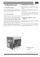
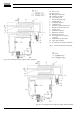
Instruction book 1 LEADING PARTICULARS 1.3 Refrigeration circuit (Figs. 2) 1.1 General description Compressor (M1) delivers hot, high-pressure refrigerant gas which flows through condenser (9) where most of the refrigerant condenses. The FD air dryers remove moisture from compressed air by cooling the air to near freezing point. This causes water to condense. The condensate is automatically drained. The air is warmed up before leaving the dryer.
Instruction book AI. Wet air inlet AO. Dry air outlet M1. Refrigerant compressor M2. Condenser fan motor S3. Fan control switch 1. Pressure dewpoint gauge 2. Insulating block 3. Condensate separator 4. Condensate trap 5. Automatic condensate drain hose 6. Manual condensate drain valve 7. Capillary tube 8. Condenser cooling fan 9. Refrigerant condenser 10. Hot gas by-pass valve 11. Air/refrigerant heat exchanger/ evaporator 12. Liquid refrigerant dryer/filter 13. Air/air heat exchanger 14.
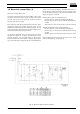
Instruction book 1.5 Electrical system (Figs. 3) FD dryers are single-phase units. Fan control switch (S3) starts fan motor (M2) as soon as the condenser pressure reaches the upper set point of the switch and will stop the fan motor when the condenser pressure decreases to its lower set point. The compressor motor has a built-in thermic protection. If the compressor motor stops without apparent reason, it will probably be the thermic protection which has tripped.
Instruction book Fig. 3b. Electrical diagram of FD30 and FD40 50 Hz C1. Start capacitor F0. Main fuses, local installation (customer's installation) H1. Indicator lamp, VOLTAGE ON H2. Indicator lamp, DEWPOINT ALARM (optional) K1. Timer (optional) M1. Compressor motor M2. Fan motor R1. Temperature sensor, dewpoint (optional) S0. Main switch (customer's installation) S1. Button, ON-OFF S3. Fan control switch S4. Electronic thermostat with display (optional) T1. Transformer (optional) Y1.
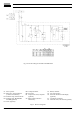
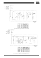
Instruction book Fig. 3c. Electrical diagram of FD40 60 Hz and FD60 Fig. 3d.
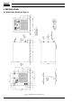
Instruction book 2 INSTALLATION 2.1 Dimension drawings (Figs. 4) Fig. 4a.
Instruction book Fig. 4b.
Instruction book Fig. 4c. Dimension drawing of FD80, FD100 and FD120 Figs. 4.
Instruction book 2.2 Installation proposal (Fig. 5) 1. FD dryer 2a. DD-type general-purpose prefilter 2c. PD-type afterfilter 3. 4. 5. 6. Air receiver with condensate drain Pressure gauge Drain pipes Dryer outlet valve 7. 8. 9. By-pass system By-pass valve Dryer inlet valve Fig. 5. Installation proposal AI. AO. M1. 1. 2. 3. 4. Air inlet Air outlet Refrigerant compressor Hot gas by-pass valve Condenser Capillary tube Liquid refrigerant dryer/filter Fig. 6.
Instruction book 2.3 Installation instructions 1. Install the dryer where the ambient air is as clean as possible and where the temperature of the air will never exceed the limits (see section 7). Keep the ventilation gratings of the dryer free. If necessary, take action to avoid external influences (wind, draughts, etc.) through the ventilation gratings of the dryer, as they may disturb the cooling air flow. 2. Connect the compressed air lines to the marked inlet and outlet pipes of the dryer (Figs.
Instruction book 3 OPERATING INSTRUCTIONS 2.4 Pictographs (Fig. 9) Safety precautions The operator must apply all relevant safety precautions, including those mentioned in this book. Altitude operation Consult Atlas Copco if operating above 3000 m. 3.1 Starting (Fig. 10) 1. 2. 3. 4. If installed, close the dryer by-pass valve. Press on-off button (S1). Open the dryer air inlet valve (customer's installation). Approx. 5 minutes later, open the dryer air outlet valve (customer's installation). 5. Approx.
Instruction book 4 MAINTENANCE 6 PROBLEM SOLVING (Figs. 2) Cooling dryers of FD type contain refrigerant HFC. 1. Pressure dewpoint too high a. Air inlet temperature too high a. Check and correct; if necessary, install a pre-cooler b. Ambient temperature too high b. Check and correct; if necessary, draw cooling air via a duct from a cooler place or relocate dryer c. Air inlet pressure too low c. Increase inlet pressure d. Dryer capacity exceeded d. Reduce air flow e. Shortage of refrigerant e.
Instruction book 7 PRINCIPAL DATA 7.1 Limitations/nominal conditions Nominal conditions Compressed air inlet pressure - HP versions . . . . . . . . . . . . . . . . . . . . . . . . . . . . . . . . . . . . . . . . . . . . - Others . . . . . . . . . . . . . . . . . . . . . . . . . . . . . . . . . . . . . . . . . . . . . . . . . Compressed air inlet temperature . . . . . . . . . . . . . . . . . . . . . . . . . . . . . Ambient temperature . . . . . . . . . . . . . . . . . . . . . . . . . . . . . . . . . . . .
Instruction book 7.3 Specific data FD30, FD40 and FD60 1) FD30 FD40 FD60 FD30HP FD40HP Volume flow at dryer inlet at nominal conditions 50 Hz 60 Hz l/s l/s 30 34 40 50 60 62 43 44 57 -- Pressure drop through dryer at nominal conditions, approx. . . . . . . . . . . . . . . . . . . . . . . . . . . . . . . . . 50 Hz 60 Hz bar bar 0.14 0.14 0.20 0.11 0.19 0.19 0.11 0.09 0.16 -- Electric power input . . . . . . . . . . . . . . . . . . . . . . 50 Hz 60 Hz kW kW 0.47 0.70 0.54 1.01 0.86 1.
No. 2920 1339 02 / DC 98.