
Product Manual


2920 1339 02
4
Instruction book
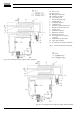
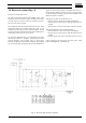
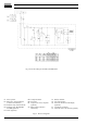
AI. Wet air inlet
AO. Dry air outlet
M1. Refrigerant compressor
M2. Condenser fan motor
S3. Fan control switch
1. Pressure dewpoint gauge
2. Insulating block
3. Condensate separator
4. Condensate trap
5. Automatic condensate drain hose
6. Manual condensate drain valve
7. Capillary tube
8. Condenser cooling fan
9. Refrigerant condenser
10. Hot gas by-pass valve
11. Air/refrigerant heat exchanger/
evaporator
12. Liquid refrigerant dryer/filter
13. Air/air heat exchanger
14. Accumulator (not for FD7 and FD16)
Figs. 2. Air and refrigerant flow diagrams
Fig. 2b. Air and refrigerant flow diagram of FD30, FD40 and FD60
Fig. 2a. Air and refrigerant flow diagram of FD7 and FD16