
Product Manual


5
2920 1339 02
Instruction book
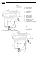
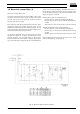
Fig. 3a. Electrical diagram of FD7 and FD16
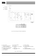
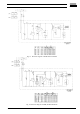
1.5 Electrical system (Figs. 3)
FD dryers are single-phase units.
Fan control switch (S3) starts fan motor (M2) as soon as the
condenser pressure reaches the upper set point of the switch
and will stop the fan motor when the condenser pressure
decreases to its lower set point.
The compressor motor has a built-in thermic protection. If the
compressor motor stops without apparent reason, it will
probably be the thermic protection which has tripped. In such
case, the compressor will restart when the motor windings have
cooled down, which may take up to 2 hours.
An electronic thermostat (Fig. 11) with display and alarm
functions is available as an option. Display (3) shows the
pressure dewpoint. The set point value, i.e. the pressure
dewpoint at which the alarm indicator lamp (H2-Fig. 3) lights
up, can be checked by pressing key (5); the value will blink for
approx. 5 seconds on the display. The differential value, i.e.
the temperature difference between alarm on and alarm off,
can be checked by pressing key (4); the value will blink on the
display for approx. 5 seconds.
Altering the set point value (indicated "L1")
- Press key (5); the current value blinks on the display.
- Press the up (1) or down (2) key until the desired value is
reached.
- To store the new value, press key (5) or wait a few seconds.
Altering the differential value (indicated "HY1")
- Press key (4); the current value blinks on the display.
- Press the up (1) or down (2) key until the desired value is
reached.
- Press key (5) or wait a few seconds to store the new value.
If the temperature increases above the preset value, alarm
indicator lamp (H2-Fig. 3) will light up.