
Install Drawing

Ed
Posi-
tion
Modified from
Date
Intr./Appd.
1
2 3
4
5
6 7
8 9
A
10
B
C
D
E
F
G
Parent 3D model
Ed . Version 3D
C
O
N
F
I
D
E
N
T
I
A
L
:
T
h
i
s
d
o
c
u
m
e
n
t
i
s
o
u
r
p
r
o
p
e
r
t
y
a
n
d
s
h
a
l
l
n
o
t
w
i
t
h
o
u
t
o
u
r
p
u
r
p
e
r
m
i
s
s
i
o
n
b
e
a
l
t
e
r
e
d
,
c
o
p
i
e
d
,
u
s
e
d
f
o
r
m
a
n
u
f
a
c
t
u
r
i
n
g
o
r
c
o
m
m
u
n
i
c
a
t
e
d
t
o
a
n
y
o
t
h
e
r
p
e
r
s
o
n
o
r
c
o
m
p
a
n
y
00
2013-05-24
9820720181
00.09
Fini wt.
Approved.
Treatment
Material
Name
Drawn by
Des checked.
Version Drwg
Scale
Blank wt
Prod checked.
Family
Blank nr.
Kg
Designation Sheet
INV
Replaces
Compare
Date
Kg
Drawing owner
/
Confidentiality Class
STATUS
Tolerances, if not indicated, according to:
ATLAS COPCO STANDARD CLASS
A1
NOT APPLICABLE
1
1
2013-01-17
9820720181
1:20
0
254,116
3
DIMENS. INSTALL.
Not Applicable
00.15
Approved
AIR15275
AII
GA18-37VSD+ FF+TRAFO
acc. to 1102 K
∆P x d x P
450 x Qc
5
1.85
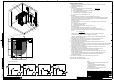
MAIN COMPONENTS
1. Compressor unit : The unit should be installed on a level floor capable of taking the
weight of the compressor.
2. Compressed air outlet valve.
3. Delivery pipe :
The max . total pipe length can be calculated from L =
L = Length of the pipe (m)
∆P = Max. allowable pressure drop (recommended 0.1 bar = 1.5psi)
d = Inner diameter of the pipe (mm)
P = Absolute pressure at compressor outlet (bar)
Qc = Free air delivery of the compressor (l/s)
4. Ventilation :
The inlet grid(s) and ventilation fan should be installed in such a way
that any recirculation of cooling air to the inlet grating of the compressor/ dryer is avoided.
The air velocity to the grid(s) has to be limited to 5m/s. The maximum air temperature at
compressor intake opening is 46 °C, min 0 °C.
Alternative 1 and 3 :
The required ventilation to limit compressor room temperature can be calculated from :
Qv = 1.06 N / ∆T
Qv = Required cooling air flow (m³/s)
N = Nominal motor power (kW)
∆T = Temperature increase in the compressor room. ( °C)
Alternative 2 and 4 :
The fan capacity should match the compressor - fan capacity
at a pressure head equal to the pressure drop caused by cooling air ducts.
When the compressor is provided with dryer (Full Feature), the required cooling air
flow is ;
Qv =
The ducting of the cooling air outlet of the dryer ("10a") should be separated of
the ducting for the cooling air outlet of AIR/OIL coolers ("10b").
The max. pressure drop over additional AIR/OIL coolers ("10b") ducting should be
limited to 15 Pa for standard fans.
5. Drain pipes to drain collector must not dip into the water. For draining of pure
condensate water, install an oil / water seperator. Consult Atlas Copco.
6. Control cubicle with monitoring panel.
7. Power supply cable to be sized and installed by a qualified electrician. In case of
IT network, consult Atlas Copco.
To preserve the protection degree of the electric cubicle and to protect its components from dust
from the environment, it is absolutely necessary to use a proper cable gland when connecting
the supply cable to the compressor.
8. Filter type DD for general purpose filtration (particle removal down to 1 micron with
a maximum oil carry over of 0.5 ppm).
A high efficiency PD filter may be installed downstream the DD filter (particle
removal down to 0.01 micron and max. oil carry over of 0.01ppm)
Should oil vapours and odours be undesirable, a QD active carbon filter should be
installed after the PD filter.
It is recommended to install by-pass pipes over each filter together with ball valves
in order to isolate the filters during service operations, without interrupting the
compressed air delivery.
9. Air receiver: A safety valve need to be foreseen on the air receiver.
10a.Cooling air outlet grating of dryer.
10b.Cooling air outlet grating of AIR/OIL coolers.
(1.16N + 0.6)
∆ T
Notes :
- All pipes should be installed STRESS FREE to the
compressor unit.
- For more information concerning air nets,
cooling systems, etc refer to the compressor
installation manual.
- For dimensions and air flow directions refer to
the AIB dimension drawings.
VENTILATION PROPOSALS
ALT. 1
ALT. 2
ALT. 3
ALT. 4
3
4
5
7
8
9
Minimum free area to be reserved
for the compressor installation
A
l
l
m
a
t
e
r
i
a
l
s
s
u
p
p
l
i
e
d
a
r
e
i
n
c
o
m
p
l
i
a
n
c
e
w
i
t
h
t
h
e
r
e
q
u
i
r
e
m
e
n
t
s
o
f
t
h
e
L
i
s
t
o
f
P
r
o
h
i
b
i
t
e
d
S
u
b
s
t
a
n
c
e
s
2
6
10a
10b
1
2
0
0
1
2
7
3
8
0
0
500 790 800
Controller