INSTRUCTION BOOK OIL-FREE SCROLL COMPRESSORS SF 15+, SF 17+, SF 22+, SFD 11+, SFD 15+, SFD 22+
Atlas Copco Oil-free scroll compressors SF 15+, SF 17+, SF 22+, SFD 11+, SFD 15+, SFD 22+ From following serial No. onwards: API 770 000 Instruction book Original instructions COPYRIGHT NOTICE Any unauthorized use or copying of the contents or any part thereof is prohibited. This applies in particular to trademarks, model denominations, part numbers and drawings. This instruction book is valid for CE as well as non-CE labelled machines.
Instruction book Table of contents 1 Safety precautions..........................................................................................................5 1.1 SAFETY ICONS................................................................................................................................... 5 1.2 SAFETY PRECAUTIONS, GENERAL...........................................................................................................5 1.3 SAFETY PRECAUTIONS DURING INSTALLATION.........
Instruction book 3.12 SERVICE MENU................................................................................................................................ 45 3.13 SETPOINT MENU...............................................................................................................................49 3.14 EVENT HISTORY MENU.......................................................................................................................51 3.15 GENERAL SETTINGS MENU...................
Instruction book 7 Adjustments and servicing procedures..................................................................... 88 7.1 AIR FILTER......................................................................................................................................88 7.2 AIR COOLER.................................................................................................................................... 88 7.3 DRIVE MOTOR............................................................
Instruction book 1 Safety precautions 1.1 Safety icons Explanation Danger to life Warning Important note 1.2 Safety precautions, general General precautions 1. The operator must employ safe working practices and observe all related work safety requirements and regulations. 2. If any of the following statements does not comply with the applicable legislation, the stricter of the two shall apply. 3.
Instruction book 1.3 Safety precautions during installation All responsibility for any damage or injury resulting from neglecting these precautions, or non observance of the normal caution and care required for installation, operation, maintenance and repair, even if not expressly stated, will be disclaimed by the manufacturer. These precautions apply to machinery processing or consuming air or inert gas.
Instruction book 13. In multiple compressor systems, manual valves must be installed to isolate each compressor. Non-return valves (check valves) must not be relied upon for isolating pressure systems. 14. Never remove or tamper with the safety devices, guards or insulation fitted on the machine. Every pressure vessel or auxiliary installed outside the machine to contain air above atmospheric pressure must be protected by a pressure relieving device or devices as required. 15.
Instruction book • • • • • 9. 10. 11. 12. 13. There are no leaks All fasteners are tight All electrical leads are secure and in good order Safety valves and other pressure relief devices are not obstructed by dirt or paint Air outlet valve and air net, i.e. pipes, couplings, manifolds, valves, hoses, etc. are in good repair, free of wear or abuse If warm cooling air from compressors is used in air heating systems, e.g.
Instruction book 10. Scrupulously observe cleanliness during maintenance and repair. Keep dirt away by covering the parts and exposed openings with a clean cloth, paper or tape. 11. Never weld or perform any operation involving heat near any oil system. Oil tanks must be completely purged, e.g. by steam-cleaning, before carrying out such operations. Never weld on, or in any way modify, pressure vessels. 12.
Instruction book 2 General description 2.1 General description Introduction SF 15+, SF 17+ and SF 22+ are stationary, oil free compressors. Dependent on the model, the compressors have 3 or 4 electric motor driven compressor modules, enclosed in a sound insulating canopy. The front door panel houses the Elektronikon Graphic controller and the emergency stop button. An electric cabinet with the electric components is installed behind the front panel.
Instruction book SF 22+ FF, rear view 1 Compressor module 3 Refrigerant dryer 2 Air cooler 4 Compressed air outlet valve SFD 22+, front view 1 Elektronikon Graphic controller 2 Electric cabinet S3 Emergency stop button Compressor element operating principle Each compressor element consists of a fixed scroll shaped housing and a scroll shaped rotor. Air enters the compressor element through inlet opening (1).
Instruction book Compressor element, typical 1 Air inlet 3 Air outlet 2 Fixed scroll 4 Orbiting scroll Compressor module The SF 15+ has four 3.7 kW modules, while the SF 17+ and the SF 22+ respectively have three or four 5.5 kW modules. The SFD 15+ has four 3.7 kW modules, while the SFD 11+ and the SFD 22+ respectively have two or four 5.5 kW modules. 3.7 kW compressor module 5.
Instruction book 1 Air filter 4 Compressor element air outlet 2 Motor 5 Safety valve 3 Compressor element 6 Temperature sensor 2920 7140 52 13
Instruction book 2.
Instruction book Text on image (1) Compressor module 1 (10) Air (2) Compressor module 2 (11) Drain (3) Compressor module 3 (12) Mechanical link (4) Compressor module 4 (13) Electrical signal (5) To cubicle (14) Electric energy (6) Refrigerant dryer (units with dryer) (15) Enclosure (7) Water separator (units without dryer) (16) Local mounting (8) Outlet (17) On control cabinet (9) Ambient temperature sensor 2920 7140 52 15
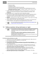
Instruction book Flow diagram of SFD 11+, SFD 15+, SFD 22+ 16 2920 7140 52
Instruction book Text on image (1) Compressor module 1 (9) Drain (2) Compressor module 2 (10) Mechanical link (3) Compressor module 3 (11) Electrical signal (4) Compressor module 4 (12) Electric energy (5) To cubicle (13) Enclosure (6) Outlet (14) Local mounting (7) Ambient temperature sensor (15) On control cabinet (8) Air Air flow Air is drawn through air filter (100) and is compressed by the compressor element (102) of each compressor module.
Instruction book Condensate drain connections (typical) Condensate drain connections on SFD 2.3 1 Automatic condensate drain outlet 2 Ambient temperature sensor 3 Manual condensate drain valve Regulating system The compressor is provided with an Elektronikon® controller module.
Instruction book 2.4 Electrical system Cubicle layout Electrical cabinet SF 15+, SF 17+ and SF 22+, typical Electrical cabinet SFD 11+, SFD 15+ and SFD 22+, typical K21, K22,... Contactor 1X0, 4X3,... Terminals Q21,Q22,... Circuit breaker T1, T4,... Transformer F1,F2,...
Instruction book 2.5 Electric diagram • The electrical installation must correspond to the applicable codes. • The mains supply and earthing lines must be of suitable size. See section Electric cable size and fuses. • The installation must be earthed and protected by fuses in each phase. • An isolating switch must be installed near the compressor. Make sure that this switch is open to isolate the compressor from the mains before carrying out any connection.
Instruction book Each compressor element is protected by a PT 1000 sensor (6) in the outlet pipe. The sensor is connected to the electronic regulator. When the maximum temperature is exceeded, the compressor element is stopped during 2 minutes before it can restart. If this happens 2 times within a time span of 2 hours, the element will be stopped during 10 minutes. If the compressor element stops a third time within the 2 hours time span, the element will be shut down and must be reset manually. 3.
Instruction book 2.7 Air dryer Flow diagram Compressed air circuit Compressed air enters heat exchanger (1) and is cooled by the outgoing, cold, dried air. Water in the incoming air starts to condense. The air then flows through heat exchanger/evaporator (2) where the refrigerant evaporates, causing the air to be cooled further to close to the evaporating temperature of the refrigerant. More water in the air condenses.
Instruction book Automatic drain The dryers are equipped with an electronic condensate drain (EWD). The condensate from the condensate trap accumulates in a collector. When the condensate reaches a certain level, it is discharged through the drain outlet (1). The condensate can also be drained by pressing the test button (2). The drain filter can be cleaned by opening the manual drain valve (3), see section Preventive maintenance schedule.
Instruction book 3 Controller 3.1 General Control panel Elektronikon® Graphic controller Introduction The controller has following functions: • • • • Controlling the compressor Protecting the compressor Monitoring components subject to service Automatic restart after voltage failure (made inactive) Automatic control of the compressor operation The controller maintains the net pressure between programmable limits by automatically starting and stopping one or more compressor modules.
Instruction book Remedy the trouble and reset the message. See also section Inputs menu. Before remedying, consult the applicable safety precautions. Shutdown warning / shutdown If the compressor element temperature exceeds the factory set warning level, the compressor element will be stopped for a short time and a warning will appear on the controller display (1) and the general alarm LED (2) will light up.
Instruction book 3.2 Control panel Control panel Parts and functions 26 Reference Designation Function 1 Display Shows the compressor operating condition and a number of icons to navigate through the menu. 2 Pictograph Automatic operation 3 Pictograph General alarm 4 Alarm LED Flashes in case of a shutdown, is lit in case of a warning condition.
Instruction book 3.3 Icons used Status icons Name Icon Description Stopped / Running When the compressor is stopped, the icon stands still. When the compressor is running, the icon is rotating.
Instruction book Name Icon Description Service Service required Main screen display Value lines display icon Chart display icon General icons No communication / network problem Not valid Input icons Icon Description Pressure Temperature Digital input Special protection System icons Icon Description Compressor element (LP, HP, ...
Instruction book Icon Description Filter Motor Failure expansion module Network problem General alarm The compressor module is running and can be stopped The compressor module is stopped and is ready to start The compressor module is awaiting the minimum stop time to expire Menu icons Icon Description Inputs Outputs Alarms (Warnings, shutdowns) Counters Test or Settings 2920 7140 52 29
Instruction book Icon Description Service Event history (saved data) Access key / User password Network Setpoint Info Navigation arrows Icon Description Up Down 3.
Instruction book Function The Main screen is the screen that is shown automatically when the voltage is switched on and one of the keys is pushed. It is switched off automatically after a few minutes when no keys are pushed. Typically, 6 different main screen views can be chosen: 1. 2. 3. 4. 5. 6.
Instruction book Text on image (1) Compressor Outlet (2) Element 2 Outlet (3) Off, Shutdown,... (text varies upon the compressors actual condition (4) Menu (5) Element 1 Outlet (6) Ambient Air • Section A shows information regarding the compressor operation (e.g. the outlet pressure, the ambient temperature or the temperature at one of the compressor element outlets). • Section B shows Status icons.
Instruction book When Chart (High Resolution) is selected, the chart shows the variation of the selected input (in this case the pressure) per minute. Also the instantaneous value is displayed. The screen shows the last 4 minutes. The switch button (icon) for selecting other screens is changed into a small Chart and is highlighted (active). When the Chart (Medium Resolution) is selected, the chart shows the variation of the selected input per hour. The screen shows the last 4 hours.
Instruction book Selection of a main screen view To change between the different screen layouts, select the far right icon in the control icons line (see value lines display icon or chart display icon in section Icons used) and press the Enter key. A screen similar to the one below opens: Select the layout required and press the Enter key. See also section Inputs menu. 3.
Instruction book Typical Main screen (2 value lines) • To go to the Menu screen, select action button Menu (1) by means of the Scroll keys and press the Enter key. Following screen appears: Text on image (1) Menu (2) Regulation • The menu screen shows a number of icons. Each icon indicates a menu item. By default, the Regulation icon is selected. The status bar shows the name of the menu that corresponds with the selected icon. • Use the Scroll keys to select the required icon (see further).
Instruction book As long as the element is stopped, an hourglass icon (1) replaces the element concerned in the main screen: Element 2 is stopped during a Minimum Stop Time due to a high element temperature If the element temperature exceeds the factory set shutdown warning repeatedly, the element will shut down, alarm LED (4) (see section Control panel) will lit and following screen will appear: Element 2 is shutdown due to repeatedly high element temperature warnings If this occurs: 1.
Instruction book Text on image (1) Element(s) (4) Problem Element (2) Warning Element 2 (5) More (3) Triggered (6) Reset Each time an element is reset manually, this will be logged in the Element Problem Reset counter: Counter screen where one element was reset manually Text on image (1) Information (4) Element Warnings (2) Trigger level (5) Element Problem Resets (3) High Temperature Warnings (6) Modify High ambient temperature If the ambient temperature is above the factory sett
Instruction book If this warning is triggered, the description of this warning can be found in the protection menu. Following screen is shown: Description of high ambient alarm in the protection menu Text on image (1) General (4) Shutd. Warn.
Instruction book 3.
Instruction book Procedure Starting from the Main screen, • Move the cursor to the action button Menu and press the Enter key. Following screen appears: Text on image (1) Menu (2) Regulation • Using the Scroll keys, move the cursor to the Inputs icon (see above, section Menu icon). • Press the Enter key.
Instruction book The first item in the list is highlighted. In this example, the Net Pressure is selected (chart icon). To change, press the Enter button again. A pop up window opens: Press Enter again to remove this input from the chart. Another confirmation pop up opens: Select Yes to remove or No to quit the current action.
Instruction book Text on image (1) 3.9 Set As Main Chart Signal Outputs menu Menu icon, Outputs Function To call up information regarding the actual status of some outputs such as the condition of the Fan motor overload contact, the general warning contact, etc. Procedure Starting from the Main screen, • Move the cursor to the action button Menu and press the Enter key.
Instruction book Text on image (1) General (4) General warning (2) General shutdown (5) Cabinet fan (3) Fan motor • The screen shows a list of all outputs with their corresponding icons and readings. If an output is in warning or shutdown, the original icon is replaced by the warning or shutdown icon respectively. 3.
Instruction book Text on image (1) Counters (4) Fan starts (2) Shutdowns element 2 (5) Module hours (3) Load relay The screen shows a list of all counters with their actual readings. 3.11 Control mode selection Function To select the control mode, i.e. whether the compressor is in local control, remote control or controlled via a local area network (LAN).
Instruction book • There are 3 possibilities: • Local control (1) • Remote control (2) • LAN control (3) After selecting the required control mode, press the Enter key on the controller to confirm your selection. The new control mode selection is now visible on the main screen. 3.12 Service menu Menu icon, Service Function • • • • To reset the service plans which are carried out. To check when the next service plans are to be carried out. To find out which service plans were carried out in the past.
Instruction book Procedure Starting from the Main screen, • Move the cursor to the action button Menu and press the Enter key. Following screen appears: Text on image (1) Menu (2) Regulation • Using the Scroll keys, move the cursor to the Service icon (see above, section Menu icon). • Press the Enter key.
Instruction book Overview Text on image (1) Overview (3) Real Time (hours) (2) Running Hours (4) Reset Example for service level (A): The figures at the left are the programmed service intervals. For Service interval A, the programmed number of running hours is 2500 hours (upper row) and the programmed number of real time hours is 8760 hours, which corresponds to one year (second row).
Instruction book Text on image (1) Service plan (4) Real time hours (2) Level (5) Modify (3) Running hours Modifying a service plan Dependant on the operating conditions, it can be necessary to modify the service intervals. To do so, use the Scroll keys to select the value to be modified. A screen similar to the one below appears: Press the Enter key. Following screen appears: Modify the value as required, using the ↑ or ↓ scroll key and press the Enter key to confirm.
Instruction book Next Service Text on image (1) Next service (3) Running hours (2) Level (4) Actual In the example above, the A Service level is programmed at 500 running hours, of which 0 hours have passed. History The History screen shows a list of all service actions done in the past, sorted by date. The date at the top is the most recent service action. To see the details of a completed service action (e.g.
Instruction book Text on image (1) Menu (2) Regulation • Using the Scroll keys, move the cursor to the Setpoint icon (see above, section Menu icon) • Press the Enter key. Following screen appears: Text on image (1) Regulation (4) Pressure band 2 High (2) Pressure band 1 High (5) Pressure band 2 Low (3) Pressure band 1 Low (6) Modify • The screen shows the actual stopping and starting pressure settings for both pressure bands.
Instruction book Text on image (1) Regulation (2) Stopping pressure • The upper and lower limit of the setting is shown in grey, the actual setting is shown in black. Use the ↑ or ↓ key of the Scroll keys to modify the settings as required and press the Enter key to accept. If necessary, change the other settings as required in the same way as described above. 3.14 Event history menu Menu icon, Event History Function To call up the last shutdown and last emergency stop data.
Instruction book Example of Event History screen • Scroll through the items to select the desired shutdown or emergency stop event. • Press the Enter key to find the date, time and other data reflecting the status of the compressor when that shutdown or emergency stop occurred. 3.15 General settings menu Menu icon, Settings Function To display and modify a number of settings. Procedure Starting from the Main screen, • Move the cursor to the action button Menu and press the Enter key.
Instruction book This screen shows again a number of icons. By default, the User Password icon is selected. The status bar shows the description that corresponds with the selected icon. Each icon covers one or more items , such as • Access level • Elements • Dryer • Fan • Filter(s) • Motor/Starter • General • Automatic restart after voltage failure • Network • Regulation • Remote For adapting certain parameters, a password may be necessary.
Instruction book 3.16 Info menu Menu icon, Info Function Shows the Atlas Copco internet address. Procedure Starting from the Main screen, • Move the cursor to the action button Menu and press the Enter key. Following screen appears: Text on image (1) Menu (2) Regulation • Using the Scroll keys, move the cursor to the Info icon (see above, section Menu icon). • Press the Enter key. The internet address appears on the screen. 3.
Instruction book Important remark: You can select different timers on one day.(up to 8 actions). It is however not possible to program 2 actions at the same time. The solution: leave at least 1 minute in between 2 actions. Example: Start Compressor: 5.00 AM, Pressure Setpoint 2: 5.01 AM (or later). Procedure Starting from the Main screen, • Move the cursor to the action button Menu and press the Enter key. Use the Scroll buttons to select the Timer icon.
Instruction book Text on image (1) Week Action Schemes (4) Week Action Scheme 3 (2) Week Action Scheme 1 (5) Week Action Scheme 4 (3) Week Action Scheme 2 • A weekly list is shown. Monday is automatically selected and highlighted in red. Press the Enter key on the controller to set an action for this day. Text on image (1) Week Action Scheme 1 (5) Thursday (2) Monday (6) Friday (3) Tuesday (7) Saturday (4) Wednesday (8) Sunday • A new window opens.
Instruction book Text on image (1) Monday (2) Modify • A new popup window opens. Select an action from this list by using the Scroll keys on the controller. When ready press the Enter key to confirm. Text on image (1) Monday (5) Stop (2) Actions (6) Pressure Setpoint 1 (3) Remove (7) Modify (4) Start • A new window opens. The action is now visible in the first day of the week.
Instruction book • A new pop up window opens. Use the ↑ or ↓ key of Scroll keys to modify the values of the hours. Use the ← or → Scroll keys to go to the minutes. Text on image (1) Monday (3) Save (2) Time (4) Modify • Press the Escape key on the controller. The action button Modify is selected. Use the Scroll keys to select the action Save. Text on image (1) Monday (3) Save (2) Start (4) Modify • A new pop-up window opens.
Instruction book Text on image (1) Monday (5) Yes (3) Are you sure? (6) Save (4) No (7) Modify Press the Escape key to leave this window. • The action is shown below the day the action is planned. Text on image (1) Week Action Scheme 1 (5) Thursday (2) Monday - Start (6) Friday (3) Tuesday (7) Saturday (4) Wednesday (8) Sunday Press the Escape key on the controller to leave this screen. Programming the week cycle A week cycle is a sequence of 10 weeks.
Instruction book Text on image (1) Week Cycle (4) Week 3 (2) Week 1 (5) Week 4 (3) Week 2 (6) Modify Press the Enter key twice to modify the first week. • A new window opens. Select the action, example: Week Action Scheme 1 Text on image (1) Week Cycle (4) Week Action Scheme 2 (2) Week 1 (5) Week Action Scheme 3 (3) Week Action Scheme 1 (6) Modify • Check the status of the Week Timer Use the Escape key on the controller to go back to the main Week Timer menu.
Instruction book Text on image (1) Week Timer (4) Status (2) Week Action Schemes (5) Week Timer Inactive (3) Week Cycle (6) Remaining Running Time • A new window opens. Select Week 1 to set the Week Timer active. Text on image (1) Week Timer (3) Week Timer Inactive (2) Week (4) Week 1 • Press the Escape key on the controller to leave this window. The status shows that week 1 is active.
Instruction book • This timer is used when the week timer is set and for certain reasons the compressor must continue working, for example, 1 hour, it can be set in this screen. This timer is prior to the Week Timer action. Text on image (1) Week Timer (2) Week Action Schemes (3) Remaining Running Time 3.18 Test menu Menu icon, Test or Function • To carry out a display test, i.e. to check whether the display and LED's are still intact.
Instruction book • Move the cursor to the action button Menu and press the Enter key (2). Following screen appears: • Using the scroll keys, move the cursor to the test icon (see above) • Press the Enter key, following screen appears: Text on image (1) Test (3) Not allowed (2) Safety Valve Test (4) Audit Data • The safety valve test can only be performed by authorized personnel and is protected by a security code. • Select the item display test and press the enter key.
Instruction book Text on image (1) Menu (2) Regulation • Using the Scroll keys, select the Settings icon (see section General settings menu). • Press the Enter key. Following screen appears: • Move the cursor to the Password icon (see above, section Menu icon) • Select Modify, using the Scroll keys and press the Enter key. Next, modify the password as required. 3.
Instruction book USB to LAN adapter • Use a UTP cable (CAT 5e) to connect to the controller (see picture below). Configuration of the network card (in Windows) • Go to My Network places (1). • Click on View Network connections (1).
Instruction book • Select the Local Area connection (1), which is connected to the controller. • Click with the right button and select properties (1). • Use the check box Internet Protocol (TCP/IP) (1) (see picture). To avoid conflicts, uncheck other properties if they are checked. After selecting TCP/IP, click on the Properties button (2) to change the settings.
Instruction book • Use the following settings: • IP Address 192.168.100.200 • Subnetmask 255.255.255.0 Click OK and close network connections. Configuration of the web server Configure the web interface (for Internet Explorer) • Open Internet Explorer and click on Tools - Internet options (2). • Click on the Connections tab (1) and then click on the LAN settings button (2).
Instruction book • In the Proxy server Group box, click on the Advanced button (1). • In the Exceptions Group box, enter the IP address of your controller. Multiple IP addresses can be given but they must be separated with semicolons (;). Example: Suppose that you already added two IP addresses (192.168.100.1 and 192.168.100.2). Now you add 192.168.100.100 and separate the 3 IP addresses by putting semicolons between them (1) (see picture).
Instruction book Click OK (2) to close the window. Viewing the controller data All screen shots are indicative. The number of displayed fields depends on the selected options. • Open your browser and type the IP address of the controller you want to view in your browser (in this example http://192.168.100.100).
Instruction book Screen shot (typical) Navigation and options • The banner shows the compressor type and the language selector. In this example, three languages are available on the controller. Compressor settings All compressor settings can be displayed or hidden. Put a check mark in front of each point of interest and it will be displayed. Only the machine status is fixed and can not be removed from the main screen. Analog inputs Lists all current analog input values.
Instruction book Counters Lists all current counter values from controller and compressor. Info status Machine status is always shown on the web interface. Digital inputs Lists all Digital inputs and their status.
Instruction book Digital outputs Lists all Digital outputs and their status. Special protections Lists all special protections of the compressor. Service plan Displays all levels of the service plan and their status. This screen shot underneath only shows the running hours. It is also possible to show the current status of the service interval.
Instruction book 3.21 Programmable settings Compressors without built-in refrigeration dryer Minimum setting Factory setting Maximum setting Starting pressure Starting pressure (8 bar compressors) bar(e) 4 7 8 Starting pressure (8 bar compressors) psig 58 101.5 116 Starting pressure (10 bar compressors) bar(e) 4 9 10 Starting pressure (10 bar compressors) psig 58 130.
Instruction book Compressors with built-in refrigeration dryer Minimum setting Factory setting Maximum setting Starting pressure Starting pressure (8 bar compressors) bar(e) 4 6.8 7.8 Starting pressure (8 bar compressors) psig 58 98.6 113.1 Starting pressure (10 bar compressors) bar(e) 4 8.8 9.8 Starting pressure (10 bar compressors) psig 58 127.6 142.1 Minimum setting Factory setting Maximum setting Stopping pressure Stopping pressure (8 bar compressors) bar(e) 4 7.8 7.
Instruction book Terminology Term Explanation ARAVF Automatic Restart After Voltage Failure. See section General. Power recovery time Is the period within which the voltage must be restored to have an automatic restart. Is accessible if the automatic restart is activated. To activate the automatic restart function, consult your supplier. Restart delay This parameter allows to programme that not all compressors are restarted at the same time after a power failure (ARAVF active).
Instruction book 4 Installation guidelines 4.1 Dimension drawing The dimension drawings can be found on the DVD or the USB, supplied with the compressor. Model Dimension drawing number SF 15+, SF 17+, SF 22+ metric 9820 7460 00–01 SF 15+, SF 17+, SF 22+ imperial 9820 7460 00–02 SFD 11+, SFD 15+, SFD 22+ metric 9820 7503 00–01 SFD 11+, SFD 15+, SFD 22+ imperial 9820 7503 00–02 Hereby a list of commonly used terms with their translation: 4.
Instruction book Installation proposal Reference Description 1 Minimum free area to be reserved for the compressor installation 2 Ventilation proposals Procedure 1. Install the compressor on a level floor, suitable for taking the weight of the compressor in a frost free and preferably low dust location. 2. Compressed air outlet valve. 3. Delivery pipe. The pressure drop over the air delivery pipe can be calculated as follows: Δp = (L x 450 x Qc1.
Instruction book Qc= Free air delivery of the compressor in l/s 4. Ventilation: The inlet grid(s) and ventilation fan should be installed in such a way that any recirculation of hot cooling air to the inlet gratings of the compressor/dryer is avoided. The air velocity to the grid(s) has to be limited to 5 m/s (16.5 ft/s). Maximum allowable pressure drop over cooling air ducts is 50 Pa (0.12 in WC). When 50 Pa is exceeded, a ventilation fan is needed at the outlet of the cooling air ducts.
Instruction book Connect the supply cable to terminals L1, L2 and L3 of terminal strip (1X0), connect the neutral conductor to terminal (N) (if applicable) and the earthing conductor to the earthing bolt (1X3).
Instruction book 4.
Instruction book 5 Operating instructions 5.1 Initial start-up Safety The operator must apply all relevant Safety precautions. Initial start-up procedure 1. Remove the red painted transport brackets (2). 2. Check the settings of the overload relays. See section Electric cable size and fuses. 3. Connect the compressor electrically. See section Electrical connections. 4. Close the condensate drain valve. See chapter Condensate management in section Flow diagram. 5. Switch on the voltage.
Instruction book 2. Switch on the voltage. 3. Close all manual condensate drain valves. 4. Press the start button (1). The compressor starts running and automatic operation LED lights up. 5. The regulator will automatically stop and start the compressor modules in function of the air pressure. 6. On compressors with integrated dryer, the nominal pressure dew point will be reached after a few minutes. The number of starts is limited to 30 starts per hour. See also section Programmable settings. 5.
Instruction book 5.4 Stopping Procedure 1. 2. 3. 4. 5.5 Press the stop button (2). Close the air outlet valve. See section Introduction. Switch off the voltage. Open the manual condensate drain valve. Taking out of operation Procedure 1. 2. 3. 4. Stop the compressor and close the air outlet valve. Switch off the voltage and disconnect the compressor from the mains. Depressurize the compressor. Open the condensate drain valve.
Instruction book 6 Maintenance 6.1 Preventive maintenance schedule Warning Before carrying out any maintenance, repair work or adjustments, proceed as follows: • Stop the compressor. • Switch off the voltage and open the isolating switch. • Press the emergency stop button (S3). • Close the air outlet valve. • Depressurize the compressor by opening the manual drain valve(s). The operator must apply all relevant Safety precautions during maintenance or repair.
Instruction book Period (note 1) Running hours (note 1) Service Plan Every 3 months (note 2) 500 -- • Check the pressure drop over the (optional) filters . • Inspect the air inlet filters: check for cleanness and damage. Replace a dirty or damaged filter with a new one. • Check the coolers. Clean by air jet if necessary. Every 6 months 1000 -- • Operate the safety valve. • Clean the compressor. • On compressors with integrated dryer: • Brush or blow off the finned surface of the condenser.
Instruction book Period (note 1) Running hours (note 1) Service Plan Operation Every 4 years 10000 B 8 bar and 116 psi compressors: • Replace the element outlet pipe and the plastic insert. See section Outlet pipe replacement (3.7 kW elements only). Note: from S/N API 772 000 onwards, a new type of 3.7 kW compressor element is used. This new element does no longer have a plastic insert in the outlet pipe and replacement is no longer required.
Instruction book Electronic components are subject to the EU Directive 2012/19/EC for Waste Electrical and Electronic Equipment (WEEE). As such, these parts must not be disposed of at a municipal waste collection point. Refer to local regulations for directions on how to dispose of this product in an environmental friendly manner.
Instruction book 7 Adjustments and servicing procedures 7.1 Air filter Procedure 3.7 kW compressor module 5.5 kW compressor module 1. Stop the compressor, close the air outlet valve and switch off the voltage. 2. Remove the filter cover (1) and the filter element. Discard damaged or clogged elements. Clean the cover. 3. Fit the new element and reinstall the filter cover. 7.2 Air cooler Cleaning Keep the cooler clean to maintain cooling efficiency. If necessary, remove any dirt with a fibre brush.
Instruction book Keep the motor free from dust for optimal cooling. 7.4 Safety valve 3.7 kW compressor module 5.5 kW compressor module Operating Operate the safety valve (5) by unscrewing the knurled cap one or two turns. Retighten the cap. Testing The valve can be tested on a separate compressed air line. If the safety valve does not open at the specified pressure, it must be replaced. No adjustments are allowed. Never run the compressor without safety valve. 7.
Instruction book Procedure 1. 2. 3. 4. Loosen motor hold-down bolts (3). Loosen the belt tension by screwing bolts (4) equally and take off the belts (1). Install new belts. Tension the belts by screwing bolts (4) equally. The tension is correct if the deflection is between 5 mm and 7 mm when exerting a force of 25 N on the belt midway between the pulleys. Make sure that the pulleys remain aligned. The maximum out-of-line is: • Maximum parallel out-of-line: 0.5 mm • Maximum angular out-of-line: 0.
Instruction book • Remove fan duct (3). 4. Clean cooling channels: • Remove dust from the cooling channels (1) by means of air jet (see next figure). • Clean the fan duct (2). 5. Reassemble the fan duct: • Put the fan duct in place. • Fit the 3 bolts and the clip. The unit is now again ready for use. 7.7 Replacement of the outlet pipe (only applicable to SF 15+ and SFD 15+) From S/N API 772 000 onwards, a new type of 3.7 kW compressor element is used on the SF 15+ and the SFD 15+.
Instruction book Replacement procedure 1. Stop the compressor, depressurize and switch off the voltage. 2. Loosen coupling (3) while immobilizing nipple (2) with a wrench. 3. Remove the outlet pipe together with the nipple. 4. Fit the elbow and the nipple to the new outlet pipe and tighten. Use only PTFE tape. 5. Fit the plastic insert in place as indicated on the drawing and assemble the outlet pipe with a maximum torque of 5 Nm (3.7 lbf.ft).
Instruction book • Contact of liquid refrigerant with the skin can cause freezing. Wear special gloves. If contacted with the skin, the skin should be rinsed with water. On no account may clothing be removed. • Fluid refrigerant can also cause freezing of the eyes. Wear safety glasses. • Avoid inhalation of refrigerant vapors. Check that the working area is adequately ventilated. Be aware that internal components of the dryer such as the pipes can reach a temperature of up to 110˚C (230˚F).
Instruction book 8 Problem solving Before carrying out any maintenance or repair, perform following steps: • Stop the compressor and switch off the voltage. • Open and lock the isolating switch to prevent an accidental start. • Isolate the compressor by closing the outlet valve. • Depressurize the system by opening the drain valve(s). Compressor Condition Fault Remedy The compressor does not start. Pressure too high. Compressor will start again when the pressure drops to the starting pressure.
Instruction book Condition Fault Remedy Condenser pressure too high or too low Fan control switch out of order Have switch replaced Condenser fan motor out of order Have fan motor inspected Ambient temperature too high Improve ventilation of compressor room, see section Installation proposal Condenser externally clogged Clean condenser Motor of refrigerant compressor stops or does not start The internal thermal protection of the motor has tripped Compressor will restart when the motor winding
Instruction book 9 Technical data 9.1 Electric cable size and fuses • The voltage on the compressor terminals must not deviate more than 10% of the nominal voltage. It is however highly recommended to keep the voltage drop over the supply cables at nominal current below 5% of the nominal voltage (IEC 60204-1). • If cables are grouped together with other power cables, it may be necessary to use cables of a larger size than those calculated for the standard operating conditions.
Instruction book Compressor type Itot (1) Max Itot (2) fuse (1) Max Q21/Q2 Q15 fuse (2) 2/Q23/ Q24 SF 17+ UL/cUL 60 Hz 460 V 33 A 40 A 37 A 45 A 12.0 A 0.43 A SF 17+ UL/cUL 60 Hz 575 V 27 A 30 A 30 A 35 A 9.6 A 0.44 A Itot (1) Max Itot (2) fuse (1) Max Q21/Q2 Q15 fuse (2) 2/Q23/ Q24 Compressor type SF 22+ IEC 50 Hz 230 V 85 A 100A 90 A 125 A 23.3 A 0.38 A SF 22+ IEC 60 Hz 380 V 53 A 63 A 57 A 63 A 14.5 A 0.26 A SF 22+ IEC 50 Hz 400 V 49 A 63 A 52 A 63 A 13.
Instruction book Compressor type Itot (1) Max Q21/Q2 fuse (1) 2 SFD 22+ IEC 60 Hz 380 V 27 A 32 A 14.5 A SFD 22+ IEC 50 Hz 400 V 25 A 25 A 12.8 A SFD 22+ UL/cUL 60 Hz 200 V 51 A 60 A 21.9 A SFD 22+ UL/cUL 60 Hz 230 V 44 A 50 A 19.0 A SFD 22+ UL/cUL 60 Hz 460 V 22 A 25 A 9.5 A 22+ UL/cUL 60 Hz 575 V 18 A 20 A 7.6 A SFD Itot (1): maximum current in the supply lines at maximum load and nominal voltage for compressors without integrated dryer.
Instruction book Installation method B2 according table B.52.1.
Instruction book Installation method F according table B.52.1.
Instruction book • For a cable of 6 mm² and installation method B2, the maximum current is 30 A x 0.8 = 24 A, which is insufficient. For a cable of 10 mm², the maximum allowed current is 50 A x 0.8 = 40 A. So 2 parallel cables of 3 x 10 mm² +10 mm² are sufficient. In case of installation method C, the maximum current of a 6 mm² cable at 40 °C is 36 A x 0.8 = 28.8 A. 2 parallel cables of 3 x 6 + 6 mm² will be sufficient. • Install 32 A fuses on each cable.
Instruction book • For supply cables larger than AWG8: use maximum allowed ampacity of the selected supply cables and compare with value in table below (see CEC Part 1 table 17) < 100 A: use AWG8 < 200 A: use AWG6 < 300 A: use AWG4 Always check the voltage drop over the cable (less than 5 % of the nominal voltage is recommended).
Instruction book 9.3 Compressor data All data specified below apply under reference conditions, see section Reference conditions and limitations. 8 bar compressors, 50 Hz Compressor type SF 15+ SF 17+ SF 22+ SFD 11+ SFD 15+ SFD 22+ Maximum working pressure (compressors without integrated dryer) bar(e) 8 8 8 8 8 8 Maximum working pressure (compressors without integrated dryer) psi(g) 116 116 116 116 116 116 Maximum working pressure (compressors with integrated dryer) bar(e) 7.75 7.
Instruction book Compressor type Dew point (compressors with integrated dryer) °F SF 15+ SF 17+ SF 22+ SFD 11+ SFD 15+ SFD 22+ 39 39 39 - SF 15+ SF 17+ SF 22+ SFD 11+ SFD 15+ SFD 22+ - - 10 bar compressors, 50 Hz Compressor type Maximum working pressure (compressors without integrated dryer) bar(e) 10 10 10 10 10 10 Maximum working pressure (compressors without integrated dryer) psi(g) 145 145 145 145 145 145 Maximum working pressure (compressors with integrated dryer) bar(e)
Instruction book Compressor type Dew point (compressors with integrated dryer) °F SF 15+ SF 17+ SF 22+ SFD 11+ SFD 15+ SFD 22+ 39 39 39 - SF 15+ SF 17+ SF 22+ SFD 11+ SFD 15+ SFD 22+ - - 116 psi compressors, 60 Hz Compressor type Maximum working pressure (compressors without integrated dryer) bar(e) 8 8 8 8 8 8 Maximum working pressure (compressors without integrated dryer) psi(g) 116 116 116 116 116 116 Maximum working pressure (compressors with integrated dryer) bar(e) 7.
Instruction book Compressor type SF 15+ SF 17+ SF 22+ SFD 11+ SFD 15+ SFD 22+ SF 15+ SF 17+ SF 22+ SFD 11+ SFD 15+ SFD 22+ 145 psi compressors, 60 Hz Compressor type Maximum working pressure (compressors without integrated dryer) bar(e) 10 10 10 10 10 10 Maximum working pressure (compressors without integrated dryer) psi(g) 145 145 145 145 145 145 Maximum working pressure (compressors with integrated dryer) bar(e) 9.75 9.75 9.
Instruction book 10 Guidelines for inspection Guidelines On the Declaration of Conformity / Declaration by the Manufacturer, the harmonised and/or other standards that have been used for the design are shown and/or referred to. The Declaration of Conformity / Declaration by the Manufacturer is part of the documentation that is supplied with this compressor.
Instruction book 11 PED (Pressure Equipment Directive) Components subject to Pressure Equipment Directive 97/23/EC (until 20/07/2016) or 2014/68/EU (from 20/07/2016 onwards) Components subject to 97/23/EC / 2014/68/EU Pressure Equipment Directive greater than or equal to category II: Part number Description Medium Pressure 0830 1009 17 Safety valve Air 9.3 bar 0830 1008 49 Safety valve Air 9.3 bar 0830 1009 18 Safety valve Air 11.
Instruction book 12 Declaration of conformity Typical example of a Declaration of Conformity document (1): Contact address: Atlas Copco Airpower n.v. P.O. Box 100 B-2610 Wilrijk (Antwerp) Belgium (2): Applicable directives (3): Standards used On the Declaration of Conformity / Declaration by the Manufacturer, the harmonized and/or other standards that have been used for the design are shown and/or referred to.
We stand by our responsibilities towards our customers, towards the environment and the people around us. We make performance stand the test of time. This is what we call — Sustainable Productivity. www.atlascopco.com No. 2920 7140 52 / 2017 - 06 - Printed in Belgium Atlas Copco Airpower NV. All rights reserved. Designs and specifications are subject to change without notice or obligation.