Instruction book for compressors GA11 - GA15 - GA18 - GA22 F1042 Important This book applies exclusively: 1. To GA11 - GA15 - GA18 - GA22 equipped with an electronic regulator as shown on the left above. For these compressors, this book must be used together with the "User manual for electronic regulator for GA5 up to GA45 compressors" 2. To GA11 - GA15 - GA18 - GA22 with an electro-pneumatic regulator as shown on the left below.
Industrial Air Division Instruction book This instruction book describes how to handle the machines to ensure safe operation, optimum efficiency and long service life. Read this book before putting the machine into operation to ensure correct handling, operation and proper maintenance from the beginning. The maintenance schedule comprises measures for keeping the machine in good condition.
Instruction book Industrial Air Division Options and special versions 1 LEADING P AR TICULARS PAR ARTICULARS 1.1 General description FullPack feature GA are stationary, single-stage, oil-injected screw compressors driven by an electric motor. GA11 up to GA22 are air-cooled. GA Standard Pack (Figs. 3) The compressors are enclosed in a sound-insulated bodywork. A control panel including the start/stop switch is provided.
Industrial Air Division Instruction book MT SV AF VI E OF BV AV 4 3 F057 Dm1 Da DP2 M1 Fig. 2a. GA Pack, motor side AF. AR. AV. BV. Ca. Co. Da. Air filter Air receiver Air outlet valve By-pass valve, oil circuit Air cooler Oil cooler Automatic condensate drain outlet Dm1. Manual condensate drain valve DP1/DP2. Oil drain plugs E. Compressor element FC. FN. Gl. M1. MT. OF. PSR19. SV. VI. VP. Vp.
Instruction book Industrial Air Division F059 F059 10 FN Fig. 2b. GA Pack/Full-feature, receiver side 1.1.3 Cooling and condensate drain systems The cooling system comprises air cooler (Ca-Fig. 1) and oil cooler (Co). The cooling air is generated by fan (FN). A moisture trap (MT-Fig. 2a) is provided in the air outlet system of GA Pack and Full-feature compressors. 1) 1).
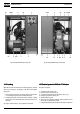
Industrial Air Division Instruction book Fig. 3b. GA18 Standard Pack, receiver side Fig. 3a. GA18 Standard Pack, motor side 1.2.2 Loading 1.3 Electrical system for GA Pack / Full-feature When the net pressure decreases to the loading pressure, solenoid valve (Y1) is energized. The plunger of the valve moves against spring force: The system comprises: 1. Control pressure is fed from air receiver (AR) via solenoid valve (Y1) to loading plunger (LP) and unloading valve (UV). 2.
Instruction book AF. AR. AV. BV. Ca. Co. Da. Air filter Air receiver Air outlet valve Oil cooler by-pass valve Air cooler Oil cooler Automatic condensate drain outlet Dm1. Manual condensate drain valve DP1/DP2. Oil drain plugs E. Compressor element E1. Control module FC. Oil filler plug FN. Fan Gl. Oil level indicator Industrial Air Division IV. LP. M1. MT. OF. OS. PT20. SV. TT90. UA. UV. VI. Vp. VP. Y1.
Industrial Air Division 1.4 Electronic control module for GA Pack / Fullfeature The control module consists of an electronic regulator and a control panel. 1.4.1 Electronic regulator (E1-Fig. 6a) The regulator has following functions: Controlling the compressor The regulator maintains the net pressure between programmable limits by automatically loading and unloading the compressor. A number of programmable settings, e.g.
Instruction book Industrial Air Division Fig. 6a.
Industrial Air Division Instruction book Fig. 6b. Electrical diagram, dryer on GA Full-feature SENSORS/LOADING SOLENOID VALVE PT20. Pressure sensor, air outlet TT11. Temperature sensor, compressor element outlet TT90. Temperature sensor, dewpoint 1) Y1. Loading solenoid valve Y2. Solenoid valve, modulating control (optional) F21. K11. K21. K22. K23. T1/T2. 1X1. 1X2. MOTORS M1. Compressor motor CONTROL MODULE (E1) I. Start button K01. Blocking relay K02. Auxiliary relay, star contactor K03.
Instruction book Industrial Air Division 1.4.2 Control panel (Fig. 7a) Indicators, keys and buttons To control the compressor and to read and modify programmable parameters, the regulator is provided with a panel including: 1 Automatic operation LED Indicates that the regulator is automatically controlling the compressor: the compressor is loaded, unloaded, stopped and restarted depending on the air consumption and the limitations programmed in the regulator.
Industrial Air Division Instruction book Fig. 8a.
Fig. 8b. Electrical diagram, GA Standard Pack, star-delta, with transformer 2920 1256 01 F1/3. Fuses F21. Overload relay, compressor motor K21. Line contactor K22. Star contactor K23. Delta contactor K24. Time relay, star/delta switch-over (10 sec) K26. Time relay, delayed motor stopping (5 min) M1. Compressor motor P1. PSR19. S1. T1. TSHH11. Y1. Y2. 1X1. 1X2.
Industrial Air Division General alarm LED (3-Fig. 7a) 1) - The LED blinks in case of a shut-down (due to either too high a compressor element outlet temperature or overload of the compressor motor); at the same time the shut-down screen appears. Remedy; see section 6. After eliminating the cause of the trouble and when the abnormal condition has disappeared, press key <> (5).
Instruction book Industrial Air Division 1.5.1 Regulator (Fig. 5b) 1.6 Air dryer on GA Full-feature (Fig. 4) The regulator loads, unloads, stops and restarts the compressor according to the air consumption, and protects the compressor and motor from overloads. The unloading and loading pressures are the opening and closing pressures respectively of switch (PSR19). See section 5.8. GA Full-feature are provided with a dryer which removes moisture from the compressed air. See Fig.
Industrial Air Division Instruction book 2 INST ALLA TION INSTALLA ALLATION 2.1 Dimension drawings (Figs. 10) Fig. 10a.
Instruction book Industrial Air Division Fig. 10b.
Industrial Air Division Instruction book 2.2 Electric cable size, settings of overload relay (F21) and main fuses Attention - Local regulations remain applicable if they are stricter than the values proposed below. - The voltage drop must not exceed 5 % of the nominal voltage. It may be necessary to use cables with a larger section than those stated to comply with this requirement. - Max. cable length = 25 m, max. ambient temperature = 40 C, cables in free air or in raceway, copper conductors. 2.2.
Instruction book Industrial Air Division 2.3 Installation proposals (Figs (Figs.. 11) Fig. 11a.
Industrial Air Division Instruction book Fig. 11b.
Instruction book Industrial Air Division Ref. Description/recommendation F or Standard P ac Pac ackk also (Fig. 11b): 1 Install the compressor on a level floor suitable for taking the weight of the compressor, and with a minimum clearance of 1.2 m above the unit except for ventilation proposals 2 and 4. 8 2 Position of compressed air outlet valve.
Industrial Air Division Instruction book 2.4 Electrical connections General - The installation must include an isolating switch near to and visible witch is open to from the compressor. Mak Makee sure that this sswitch isolate the compressor from the mains before carrying out any connection connection. - See section 2.2 for the size of the electric cables. - The installation must be earthed and protected against short circuits by fuses of the inert type in each phase. See section 2.2.
Instruction book Industrial Air Division 2.5 Pictographs Fig. 13 shows typical examples of pictographs used for GA compressors. See also Fig. 9. 1. 2. 3. 4. 5. 6. 7. 8. 9.
Industrial Air Division 3 OPERA TING INSTR UCTIONS OPERATING INSTRUCTIONS 3.1 Before initial start-up 3.1.1 Safety precautions The operator must apply all relevant safety precautions, including those mentioned in this book. 3.1.2 User manual (GA Pack / Full-feature only) Read the "User manual for electronic regulator for GA5 up to GA45 compressors" to familiarize yourself with all regulator functions. 3.1.
Instruction book 3. Check the voltage selecting wires at the primary side of transformer (T1-Fig. 5a) 1) 1), the setting of compressor motor overload relay (F21), and that overload relay (F21) is set for automatic resetting. 4. Fit air outlet valve (AV-Figs. 2 and 3). Close the valve. Connect the air net to the valve. 5. Fit valve (Dm1-Fig. 2a). Close the valve. Connect the valve to a drain collector. 2) 6. Connect the automatic drain outlet (Da-Fig. 2a) to a drain collector. 2) 7.
Industrial Air Division - the maximum allowable unloading pressure the outlet pressure the compressor element outlet temperature the dewpoint temperature (on Full-feature compressors) the status of the motor overload protection (normal or not) the total running and loading hours 3.5 Manual control for GA Pack / Full-feature (Fig. 7a) 1) Normally, the compressor runs in automatic operation, i.e. the electronic regulator loads, unloads, stops and restarts the compressor automatically.
Instruction book Industrial Air Division 4.2 Preventive maintenance schedule for the compressor 1) Attention For overhauling or carrying out preventive maintenance, service kits are available. See section 4.7. Atlas Copco offers several types of Service contracts, relieving you of all preventive maintenance work. For more details, consult your nearest Atlas Copco representative. The schedule comprises a summary of the maintenance instructions.
Industrial Air Division Instruction book Notes 1. More frequently when operating in a dusty atmosphere. 2. Use an oil filter as specified in the Parts list. 3. Special Atlas Copco oil for screw compressors keeping the compressor in excellent condition. 4. Damaged flexibles must be replaced immediately. 5. It is strongly recommended to use Atlas Copco Roto-injectfluid. 6. Consult the User manual for the electronic regulator for resetting the service timer (not for GA Standard Pack). 7.
Instruction book Industrial Air Division 4.6 Storage after installation Run the compressor twice a week until warm. Load and unload the compressor a few times. Testing The valve can be tested on a separate compressed air line. If the valve does not open at the pressure marked on the valve, consult Atlas Copco. No adjustments are allowed. Never run the compressor without safety valve. If the compressor is stored without running from time to time, protective measures must be taken. Consult Atlas Copco.
Industrial Air Division Instruction book by its own outlet pressure. The valve is factory-set to keep the effective evaporator pressure at no-load at a minimum of 2 bar (29 psi) 1) 1), which corresponds to 1 C (34 F). If necessary, have the valve adjusted. 5.8 Load/unload pressure switch (PSR19-Figs. 3) on GA Standard Pack The switch allows the operator to select the unloading pressure and the pressure difference between the unloading and loading pressures.
Instruction book Industrial Air Division Fig. 16a. Switch MDR 53/11 Fig. 16b. Switch MDR 53/16 Example (see Fig. 16a): - unloading pressure(e): 8 bar loading pressure(e): adjustable between 5 bar and 7.6 bar Figs. 16. Pressure difference adjustment ranges 6 PR OBLEM SOL VING PROBLEM SOLVING Attention - - Message Action System failure 10 or 106 Switch off the voltage. Check the terminals on connector (2X1) and emergency stop button (S3) for correct connection.
Industrial Air Division Mechanical faults and suggested remedies (Fig. 4) 1. Compressor starts running, but does not load after a delay time a. Solenoid valve (Y1) out of order a. Have valve inspected b. Inlet valve (IV) stuck in closed position b. Consult Atlas Copco c. Leak in control air flexibles c. Have leak repaired d. Minimum pressure valve (Vp) leaking (when net is depressurized) d. Consult Atlas Copco 2. Compressor does not unload, safety valve blows a. Solenoid valve (Y1) out of order a.
Instruction book 7 PRINCIP AL D ATA PRINCIPAL DA Industrial Air Division 7.3 Dryer control switches and refrigerant specifications on GA Full-feature 7.1 Readings 7.1.1 Readings on display on GA Pack / Full-feature (4-Fig. 7a) 1) Ref.: Air outlet pressure Reading: Modulates between programmed unloading and loading pressures. Shown: On main display (Fig. 7b), when: - switching on voltage - selecting main display with keys <
Industrial Air Division Instruction book 7.4.3 Specific data of 7.5 bar compressors 1) Compressor GA11 GA15 GA18 GA22 Frequency . . . . . . . . . . . . . . . . . . . . . . . . . . . . . . . . . . . . . . . . Hz Maximum (unloading) pressure - Pack/Standard Pack . . . . . . . . . . . . . . . . . . . . . . . . . . . . . . . bar(e) - Full-feature . . . . . . . . . . . . . . . . . . . . . . . . . . . . . . . . . . . . . . bar(e) Nominal working pressure . . . . . . . . . . . . . . . . . . . . . . . . . .
Instruction book Industrial Air Division Compressor GA11 GA15 GA18 GA22 - Full-feature . . . . . . . . . . . . . . . . . . . . . . . . . . . . . . . . . . . . . . kW Temperature of air at outlet valve - Pack/Standard Pack . . . . . . . . . . . . . . . . . . . . . . . . . . . . . . . C - Full-feature . . . . . . . . . . . . . . . . . . . . . . . . . . . . . . . . . . . . . . C Motor shaft speed . . . . . . . . . . . . . . . . . . . . . . . . . . . . . . . . . . r/min Oil capacity . . . . . . . . . . .
Industrial Air Division Instruction book 7.4.8 Specific data of 150 psi compressors 1) Compressor GA11 GA15 GA18 GA22 Frequency . . . . . . . . . . . . . . . . . . . . . . . . . . . . . . . . . . . . . . . . Hz Maximum (unloading) pressure - Pack/Standard Pack . . . . . . . . . . . . . . . . . . . . . . . . . . . . . . . bar(e) - Full-feature . . . . . . . . . . . . . . . . . . . . . . . . . . . . . . . . . . . . . . bar(e) Nominal working pressure . . . . . . . . . . . . . . . . . . . . . . . . . .