6060560 │COMPRESSOR 460/60/3 116CFM │Cu ┌─Item Text ──────────────────────────────────────────────────────────────────┐ │ COMPRESSOR 460/60/3 116 CFM 150 PSI │ │ │ │ Manufacturer: ATLAS COPCO │ │ Mfr Part No : GA22FF │ │ Size : 116 CFM @ 150 PSI │ │ Add'l Info : ROTARY SCREW, SINGLE STAGE, OIL INJECTED, │ │ AIR COOLED, FULL FEATURE UNIT │ │ WITH INTEGRATED REFRIGERATED DRYER, │ │ COMPRESSOR FAILURE DRY CONTACTS. │ │ 30 HP, │ │ 460V, 3 PHASE, 60 HZ │ │ 40 IN LONG X 31 IN WIDE X 71 IN HIGH 1318 LBS.
Atlas Copco Stationary Air Compressors GA5 up to GA90C User Manual for Elektronikon regulator Important 1. This Manual applies exclusively to the compressors equipped with the Atlas Copco Elektronikon regulator. 2. This Manual must be used together with the relevant Instruction books for the compressors. • Copyright 1999, Atlas Copco Airpower n.v., Antwerp, Belgium. Any unauthorized use or copying of the contents or any part thereof is prohibited.
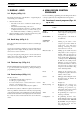
User manual Contents Page 1 General description . . . . . . . . . . . . . . . . . . . . . . . . . . . 3 1.1 Controlling the compressor . . . . . . . . . . . . . . . . . . 3 1.2 Protecting the compressor . . . . . . . . . . . . . . . . . . . 3 1.2.1 Shut-down and motor overload . . . . . . . . . . 3 1.2.2 Shut-down warning . . . . . . . . . . . . . . . . . . . 3 1.2.3 Control of motor rotation direction . . . . . . . 3 1.2.4 Warning . . . . . . . . . . . . . . . . . . . . . . . . . . . . 3 1.
User manual 1 GENERAL DESCRIPTION The electronic regulator automatically controls the compressor, i.e.
User manual 2 CONTROL PANEL 1 11 2 12 4 6 2.1 Indicators, keys and buttons (Fig. 2.1) Ref. Designation Function 1 Automatic operation LED Indicates that the regulator is automatically controlling the compressor: the compressor is loaded, unloaded, stopped and restarted depending on the air consumption and the limitations programmed in the regulator. 2 Voltage on LED 3 General alarm LED Is alight if a warning or shut-down warning condition exists or if a sensor is out of order. See section 7.
User manual 3 DISPLAY - KEYS 3.1 Display (4-Fig. 2.1) The display has four lines of 16 characters. A typical display is shown in Fig. 2.2. It indicates: 1. On the first three lines: - The name of the sensor of which the actual reading is displayed - The unit and actual reading of the sensor - Messages regarding the compressor operating condition (compressor loaded, off, etc.), a service need (e.g. for the oil filter and air filter) or a fault (e.g. shut-down) 2.
User manual Fig. 4.1.
User manual Fig. 4.2.
User manual Fig. 4.3.
User manual Program See section Function Saved data 15 Calling up the saved data: last shut-down, last emergency stop, longest load, longest unload. MORE 16 MANUAL 17 LOAD/UNLOAD Quick look at the actual status of the compressor: automatic or manual control, local or remote control, start/stop timer on or off, max. pressure, delivery air pressure and temperature, dewpoint, motor overload status, running and loading hours, on GA55 up to GA90C also the pressure difference over the oil separator.
User manual Line Indicates Remarks 3 Indicates that one of the monitored components needs servicing. Consult section 10 to find out the exact cause for this message. 3 Service required Sensor error Indicates that a sensor is out of order: On GA5 up to GA45: - Temperature sensor at the outlet of the compressor element - Outlet pressure transducer - On Full-feature compressors, the dewpoint sensor - Stop the compressor.
User manual 7.2.1 No shut-down warning message or shut-down message exists In this case, LED (3-Fig. 2.1) is out and the message on the display indicates that all conditions are normal (Fig. 7.1): Delivery air bar *Shutd Menu 7.0 ** F1 All conditions are OK F2 F3 Fig. 7.1. Example of a status data screen F2 Element outlet Shdw C Menu ** F1 LED (3-Fig. 2.1) blinks and the shut-down screen (Fig. 7.2) automatically appears on the display if the compressor is shut down.
User manual 3. Looking for more details is carried out in a similar way as described in steps 3 and 4 of section 7.2.3. If necessary, stop the compressor and remedy the fault. 8 MEASURED DATA SUBMENU: Calling up measured data 7.3 Shut-down reset 8.1 Function 1. Suppose that the shut-down screen as shown in Fig. 7.2 exists. 2.
User manual - temperature A shut-down (<>) level is programmed, i.e. <<110>> degrees celsius maximum (<>) The actual temperature is <<85>> degrees celsius The key <> can be used to look at the warning level, see step 7. The display indicates that a shut-down warning (<>) level is programmed, i.e. 100 degrees celsius maximum (<>). Press the key <> to return to the screen of Fig. 8.2. 5. On Full-feature compressors only, the scroll keys can be used to show the dewpoint.
User manual 10 SERVICE SUBMENU: Calling up and resetting service messages 10.1 Function To call up and reset service messages for following monitored components: oil, oil filter, oil separator and air filter. 10.2 Calling up service messages 1. Activate the main menu by pressing the key <
User manual 12 MODIFY SETTINGS SUBMENU: Modifying settings for regulation, protection and service 12.1 Function To modify a number of programmable parameters, including: 1 Regulation settings: - Unloading pressure - Loading pressure - Motor running time in star - Load delay time - Number of motor starts/hour - Minimum stop time (i.e.
User manual Loading press bar Prog Lim Canc Element outlet Shd C Menu F1 F2 F3 F1 "7.0" Fig. 12.2. Example of a modifying screen (regulation settings) 4. Modify the value by means of the scroll keys (6-Fig. 2.1). Figures 12.1 and 12.2 show the displays when changing the loading pressure from 6.6 bar into 7.0 bar. 5. Press the key <> to program the new value or the key <> to cancel the modification operation (the original value will be retained).
User manual The example in Fig. 12.7 indicates: - On line 1, the name of the sensor (Compressor <>) - On line 2, the type of parameter (<> shut-down <>) - On line 3, the unit (<>) and the actual value (<<0>>) 9. If it should be necessary to modify the nominal setting of 0 seconds, first consult section 18 before pressing the key <> (modify) and then using the scroll keys (6-Fig. 2.1) for modifying. 10.
User manual 2. Press the key <> (select): a screen similar to the one shown below appears (Fig. 12.13). 9. Consult steps 6 and 7 if modifying is desired. 12.5 Modifying service settings Cool water out Warn C Menu Mod F1 F2 Max 60 45 ↓ F3 1. Call up the modify settings submenu and select the option <>. See section 12.2. 2. The first option of a list of programmable service settings is shown. See section 12.1 for the list of all programmable parameters.
User manual 13 TIMER SUBMENU: Programming compressor start/stop commands programmed start/stop commands will not be executed (but remain in the memory of the regulator). 13.1 Function 13.2.3 To program up to 56 start/stop commands for the compressor. 1. Press the key <> on the timer screen. A typical display is shown in Fig. 13.2. 13.2 Procedure 1. Activate the main menu by pressing the key <
User manual indication and the start/stop indication. See Figs. 13.6 and 13.7. 5. Press the key <> (program) to program the new command or the key <> (cancel) to quit without reprogramming. 6. The regulator will ask if it is desired to change more commands. Prog 06:00 start 17:00 stop 07:00 start Canc F1 F2 "Mon" Make sure that the timer function is activated (<>). If not, the programmed start/stop commands will not be executed. 13.2.
User manual 14 CONFIGURATION SUBMENU: 15 SAVED DATA SUBMENU: Calling up Reprogramming time, date, compressor data saved by display language, units, motor regulator start mode and date format 14.1 Function To reprogram a number of parameters.
User manual shown (the data reflect the condition of the compressor at the moment of shut-down): - Time - Date - Duration of longest load or unload period (if these data are selected) - Number of running hours - Number of loading hours - Number of motor starts - Outlet pressure - Compressor element outlet temperature - Condition of the motor overload function 3. Press the key <
User manual 17 MANUALLY LOADING/ UNLOADING 17.1 Function To load and unload the compressor manually. Normally, the compressor is running in automatic operation, i.e. the electronic regulator loads, unloads, stops and restarts the compressor automatically. LED (1-Fig. 2.1) is then alight. If required, the compressor can be unloaded manually. In this case, the compressor is switched out of automatic operation, i.e. the compressor remains running unloaded unless it is loaded again manually. 17.
User manual Minimum Nominal Maximum Unloading pressure 3) 13 bar Pack . . . . . . . . . . . . . . . . . . . . . . . . . . . . . . . . . . . . . . . . . . . . . . 13 bar Full-feature . . . . . . . . . . . . . . . . . . . . . . . . . . . . . . . . . . . . . . . . 10 bar Pack . . . . . . . . . . . . . . . . . . . . . . . . . . . . . . . . . . . . . . . . . . . . . . 10 bar Full-feature . . . . . . . . . . . . . . . . . . . . . . . . . . . . . . . . . . . . . . . . 7.5 bar Pack . . . . . . . . . . . . . . .
User manual 18.3 Service settings Minimum Nominal Maximum Oil filter lifetime (running hours) . . . . . . . . . . . . . . . . . . . . . . . . . . . . . hr 0 4000 5) Oil lifetime (running hours) . . . . . . . . . . . . . . . . . . . . . . . . . . . . . . . . . hr 0 4000 7) Air filter (running hours) . . . . . . . . . . . . . . . . . . . . . . . . . . . . . . . . . . . hr 0 4000 Oil separator (running hours) for GA5 up to -10 . . . . . . . . . . . . . . . .
User manual Notes: ............................................................................................................................................................................................................................ ............................................................................................................................................................................................................................ ..................................................
User manual Notes: ............................................................................................................................................................................................................................ ............................................................................................................................................................................................................................ ..................................................
Instruction book Notes: ............................................................................................................................................................................................................................ ............................................................................................................................................................................................................................ .............................................