ATLAS SLIM POWER WALL Instruction Manual V1.
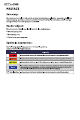
1.Safety precautions 1.1 General security Statement When installing, operating and maintaining the equipment, please read this manual first and follow the signs on the equipment and all safety precautions . The “notice", "attention", "warning" and "danger" in the manual do not represent all safety precautions to be obser ved, but only supplement all safety precautions.
◆ When installing the equipment, use tools to tighten the screws. ◆ Paint scratches during equipment transportation and installation must be repaired in time. It is strictly prohibited to expose the scratched parts to the outdoor environment for a long time. ◆ Do not open the main panel of the device without the permission of the manufacturer. ◆ In any case, do not change the structure and installation sequence of the equipment without the permission of the manufacturer.
◆ Do not stand or lean on or sit on the equipment. ◆ Do not damage each module of the equipment. ◆ When installing the batter y module, if the batter y module falls or is strongly impacted, the equipment will be damaged. It is strictly prohibited to continue to use, other wise there will be safety risks (cell leakage, electric shock injur y, etc.). Treatment measures for batter y leakage In case of electrolyte leakage, avoid contact with leaked liquid or gas.
1.2 Personnel requirements ◆ The personnel responsible for the installation and maintenance of this equipment must understand various safety precautions and master the correct operation methods. ◆ Only qualified professionals or trained personnel are allowed to install, operate and maintain the equipment. ◆ Only qualified professionals are allowed to dismantle safety facilities and overhaul equipment.
◆ If the equipment has multiple inputs, all inputs of the equipment shall be disconnected, and the equipment can be operated only after the equipment is completely powered off. Wiring requirements ◆ The use of the cable in high temperature environment may cause aging and damage of the insulating layer. The distance between the cable and the peripher y of the heating device or heat source area shall be at least 30mm.
2.2 Appearance description + 9 10 RST ADS DO RS485 CAN RS232 RS485 12 34 65 8 7 11 - ESI 12 NO.
2.3 System diagram 7 ( C) Inverter (A) PV module (B) DC switch (D) AC switch (E) Power Distribution Box (F) Intelligent power collector (G) Power grid (H) Batter y(WALL) (I) GSM (J) WIFI (K) Router (L) Bluetooth (M) APP (N) Load Explanation ◆ The input and output of the batter y energy storage system are connected to the energy storage port of the inverter.
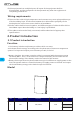
3.Product installation 3.1 Unpacking inspection Please confirm whether the outer package of the product is damaged before unpacking. After unpacking, please carefully check the product for damage or missing accessories. In case of damage or missing accessories, please contact the supplier directly for assistance. MSD A C B S D E F 8 NO.
◆ The installation location shall be reasonably away from the fire source. ◆ The installation location shall not be accessible by the children. ◆ The installation location shall be sufficiently away from water sources, such as water tap, sewer pipe, sprinkler etc., to avoid water infiltration. ◆ The installation wall shall be strong enough to carr y the weight of the batter y for a long time, please follow local standard or best practice guidelines.
3.3 Ladder use safety ◆ Wooden ladder or FRP ladder shall be used when power climbing operation may be involved. ◆ When using the herringbone ladder, the pulling rope must be firm, and someone must hold the ladder during operation. ◆ Before using the ladder, please confirm that the ladder is intact, the bearing weight of the ladder meets the requirements, and over weight is strictly prohibited.
◆ Lock the nut and fix the batter y mounting bracket. Then hang the batter y on the mounting bracket. ◆ After adjusting the position of the batter y, lock the M6 * 40 screw at the top of the support, fix the batter y, and place the batter y to slide. 30cm ◆ installation is complete. 11 30cm 30cm 30cm 4.Electrical connection 4.1 Cable connection A B Anderson connector is used on the DC input side of the batter y energy storage system.
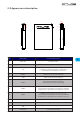
NO. Cable diameter Terminal Description Length A Anderson/SC25-8 25mm² 1-3m Used for connection between batter y and inverter B Anderson 25mm² 1-3m For batter y parallel connection 4.2 Communication line connection 4.2.1 RS485 Communication point definition PIN RS485 1 RS485_B 2 RS485_A 4.2.2 CAN Communication point definition 9 16 PIN CAN 8P8C 1 CANL 12_CANL 2 CANH 13_CANH 4.2.
◆ Different inverter communication protocols have different pin definitions. Please pay attention to the compatibility between the batter y and inverter CAN/RS485 communication line. 4.
Description Cable color Description Cable color DC positive wire RJ45 Communication Line RS485/CAN communication DC negative wire RJ11 Communication Line 4.4.
◆ The inverter only needs to communicate with the host (Pack1). ◆ When multiple batteries are connected with multiple inverters, it is best to connect through the combiner box. If it is not connected through the combiner box, the wiring mode shall be confirmed with the manufacturer's agent. And the cable from each batter y to the inverter remains the same length. Notice ◆ Batteries are not allowed to be connected in series.
5.2.2 RST key description NO. Description Mode 1 Fault 2 Dormancy 3 Reset BMS is in sleep state, press the key (3 ~ 6S) and release it, the protection board is activated, and the LED indicator lights up successively from "run" for 0.5 seconds. BMS is in the active state. Press the key (3 ~ 6S) and release it, the protection board is dormant, and the LED indicator lights up successively from the lowest power light for 0.5 seconds. BMS is active.
5.3 wireless kit(Optional) The wireless kit is divided into three modules: ◆ Bluetooth ◆ WIFI ◆ GSM Each module is an independent module, which module can be confirmed by label. Outline drawing of wireless Kit Connecting wireless kit: ◆ Insert the module into the batter y wireless kit port, download the wireless kit app, and register the account after installation. ◆ After turning on Bluetooth / WiFi / GSM, click Add device. Explanation ◆ The maximum connection range of Bluetooth is only 12 meters.
User registration Switch to ”ME“ in the lower right corner of APP. ◆ Click the avatar position to register. ◆ “Language”for language switching, supporting 3 languages. Add device Click "home" in the lower left corner of the app to switch to the add product module. ◆ Click "Add Device"or ”+” to add products. The “Message” is after-sales ser vice.
Alarm ◆ You can view batter y alarm related information. NO. Items Description NO.
6.Batter y Monitoring 6.1 Software running environment The software runs on PC and it is compatible to use Windows operating system. The system environment requires the support of Microsoft .Net Framework version 2.0 or above. Please confirm that it has been installed before use. The installation is as follows: ◆ Download Microsoft .Net framework ◆ Double click the downloaded program to install it ◆ This software does not need to be installed independently, but only needs to meet the environment.
◆ Poor communication line or wrong wiring: Method: replace the communication line or correct the wrong wiring. ◆ The computer USB interface is not recognized: Method: change a USB interface ◆ Drive not installed: Method: install the driver corresponding to the communication line. Method for judging whether the communication line driver has been installed: ◆ Check whether there is a relevant COM port in the "serial port" drop-down of the upper computer. If it is not found, it may not be installed.
NO. Item 8 Tr y connect 9 Pack serial number group Description Tr y to connect: search for available serial ports and open them. The data key, which is the package serial number, displays the package being read and presented on the current interface with white words on a blue background; Administrator 11 password column “Auto" key, alternate function buttons. Available when FF is selected for pack in 3 and monitoring is started, i.e.
◆ Get administrator privileges: Enter the administrator password in the "administrator password" input box at the bottom right of the interface. After correctly entering the password, the input box turns green. At this time, you have obtained administrator permission. 6.3.2 Parallel monitoring ◆ Interface: Click the main interface tab [Multi Monitoring] to enter the interface. 23 ◆ To the Bottom: Check "To the Bottom" at the bottom left to display the monitored real-time data in the data area.
Pause / continue: when reading, click "pause" to read, and then click again to continue reading. Save record: save the record on the interface to local. Delete record: delete the storage record of BMS board. Explanation when reading, the prompt "no more data" indicates that the reading has been completed. 6.3.4 Parameter setting ◆ Interface: Click the main interface tab [Parameter Setting] to enter the interface. ◆ Function: Read parameters: read all parameters in the interface.
Write parameters: over write BMS parameters. This operation requires administrator privileges. Restore default parameters: restore all parameters to the default parameters. The default parameters are from the preset parameters in BMS. This operation requires administrator privileges. Import parameters: read the data in the local file into this interface. Note: the data is only read on the interface and has not been written into the BMS. If you need to write, please execute the write operation. 6.3.
6.4 Replacing inverter protocol on batter y monitoring(Optional) Software running environment This function can only be realized by installing the protocol conversion board. Before using this function, please confirm whether the protocol conversion board is installed on this batter y. This software does not need to be installed independently, but only needs to meet the environment. Double click the main program icon to run it. ◆ Connect the computer to the batter y via the USB-RS485 communication cable.
7.Maintenance and replacement ◆ Please maintain the equipment when you are familiar with and understand the contents of this manual and have appropriate tools and test devices. ◆ Before carr ying out maintenance work , please power down the equipment first, then follow the instructions of the delayed discharge label and wait for the corresponding time to ensure that the equipment has been powered down before operating the equipment.
◆ Batter y maintenance shall be performed or super vised by personnel familiar with the batter y and its required precautions. ◆ After the batter y production test is completed, it needs to be supplemented to 30-50% SOC at least before storage. 9.Warranty products Requirement: During the warranty period, the company requires customers to provide invoices and dates for purchasing products.