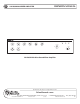
OWNER'S MANUAL AA120/AA240 MIXER AMPLIFIER Signal Input 1 Input 2 Input 3 Input 4 Input 5 Peak Power Input 6 Power Master n On Off n Bass Treble AA120/AA240 Atlas Sound Mixer Amplifier Specifications are subject to change without notice AtlasSound.com 1601 JACK MCKAY BOULEVARD ENNIS, TEXAS 75119 U.S.A. • ©2006 ATLAS SOUND LP Printed in U.S.A.
OWNER'S MANUAL AA120/AA240 MIXER AMPLIFIER TABLE OF CONTENTS Safety Instructions………………………………………………………………………………………………….2 Introduction, Features, and Applications......................................................................……………………..3 Safety Precautions......................................................................……………………...………………………4 Front Panel Description…………………………………………………………………………………………....6 Rear Panel Description…………………………………………………………………………………………….
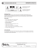
OWNER'S MANUAL AA120/AA240 MIXER AMPLIFIER 4HE LIGHTING FLASH WITH ARROWHEAD WITHIN A TRIANGLE IS INTENDED TO TELL THE USER THAT PARTS INSIDE THE PRODUCT ARE A RISK OF ELECTRIC SHOCK TO PERSONS #!54)/. 2)3+ /& %,%#42)# 3(/#+ $/ ./4 /0%. !44%.4)/. | 2)315% $% $%#(!2'% %,%#42)15% .% 0!3 /562)2 4HE EXCLAMATION POINT WITHIN A TRIANGLE IS INTENDED TO TELL THE USER THAT IMPORTANT OPERATING AND SERVICING INSTRUCTIONS ARE IN THE PAPERS WITH THE APPLIANCE 7!2.).
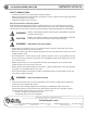
OWNER'S MANUAL AA120/AA240 MIXER AMPLIFIER SAFETY PRECAUTIONS • • • Read the instructions very carefully before using this product. Observe the instructions in this manual as conventions of safety; symbols and messages regarded as important precautions are included. Retain this manual for future reference.
OWNER'S MANUAL AA120/AA240 MIXER AMPLIFIER • • • • • If water or any metallic objects falls, into the product. • If the power supply cord is damaged in any way. • If the unit is malfunctioning. Do not insert or drop metallic objects or flammable materials into the ventilation holes of the product's cover, as this may result in electric shock or fire. Do not place any containers with liquid or metallic objects on the top of the product.
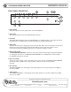
OWNER'S MANUAL AA120/AA240 MIXER AMPLIFIER FRONT PANEL DESCRIPTION Input 1 Input 2 Input 3 6 Input 5 Input 4 5 4 3 Signal Peak Power 2 Input 6 Power Master n On Off 1 n Bass Treble 7 8 1. Power Switch This push on/push off switch applies power to the AA120/AA240. 2. Power LED This LED will illuminate when the AA120/AA240 is turned on. 3.
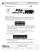
OWNER'S MANUAL AA120/AA240 MIXER AMPLIFIER 10 9 REAR PANEL DESCRIPTION Unswitched Outlet 120V AC 60Hz Max 500W Outlet Breaker 125V AC 4A Push Reset Bridge In/Out G Zone 2 Out Remote VCA Mute 1W 8¡ 600¡ Sel + + Zone 2 Level + Pre Out Line Out Tape Out Input 5 Trim Input 4 Trim Input 6 Speaker Output 120W 8¡ 25V 70V Input 1 Sens Input 1 Trim Input 2 Trim 1 2 100V 4 5 6 Input 4 Input 3 Input 2 Off Off On On 2 3 4 5 6 7 Input 5 Input 4 Input 3 Input 2 Input 1 Ph
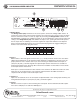
OWNER'S MANUAL AA120/AA240 MIXER AMPLIFIER 1 2 3 4 5 6 7 8 Input 6 Input 5 Input 4 Input 3 Input 2 Input 1 Phantom VCA 100mV Line Line Line Line Tel/Line Off Master 300mV Mic Mic Mic Mic Mic On Input 6 Sens Dipswitch 6 - When set the "Tel/Line" position, Input 1 sensitivity is suitable for telephone paging and line level signals. When set to the "Mic" position, the sensitivity is set for microphone signals.
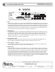
OWNER'S MANUAL AA120/AA240 MIXER AMPLIFIER 17 16 15 14 18 Unswitched Outlet 120V AC 60Hz Max 500W Outlet Breaker 125V AC 4A Push Reset Bridge In/Out G Zone 2 Out Sel + Remote VCA Mute 1W 8¡ 600¡ + Pre Out Zone 2 Level + Line Out Tape Out Input 5 Trim Input 4 Trim Input 6 Speaker Output 120W Com 8¡ 25V 70V Input 3 Trim Input 1 Sens Input 1 Trim Input 2 Trim 1 2 1 2 3 4 5 6 7 Input 6 Input 5 Input 4 Input 3 Input 2 Input 1 Phantom VCA Line Line Line Line Tel/Line
OWNER'S MANUAL AA120/AA240 MIXER AMPLIFIER 19 Unswitched Outlet 120V AC 60Hz Max 500W Outlet Breaker 125V AC 4A Push Reset Bridge In/Out G Zone 2 Out Sel + Remote VCA Mute 1W 8¡ 600¡ + Pre Out Zone 2 Level + Line Out Tape Out Input 5 Trim Input 6 Speaker Output 120W 8¡ 25V 70V Input 2 Trim Input 1 Sens Input 1 Trim 1 2 100V 4 5 6 Input 4 Input 3 Input 2 Off Off On On 2 3 4 5 6 7 Input 5 Input 4 Input 3 Input 2 Input 1 Phantom VCA Line Line Line Line Tel/Li
OWNER'S MANUAL AA120/AA240 MIXER AMPLIFIER Unswitched Outlet 120V AC 60Hz Max 500W Outlet Breaker 125V AC 4A Push Reset Bridge In/Out G Zone 2 Out Sel + Remote VCA Mute 1W 8¡ 600¡ + Pre Out Zone 2 Level + Line Out Tape Out Input 5 Trim Input 4 Trim Input 6 Speaker Output 120W Com 8¡ 25V 70V Input 3 Trim Input 1 Sens Input 1 Trim Input 2 Trim 1 2 1 2 3 4 5 6 7 Input 6 Input 5 Input 4 Input 3 Input 2 Input 1 Phantom VCA Line Line Line Line Tel/Line Off Master O
OWNER'S MANUAL AA120/AA240 MIXER AMPLIFIER 30 Unswitched Outlet 120V AC 60Hz Max 500W Outlet Breaker 125V AC 4A Push Reset Bridge In/Out G Zone 2 Out Sel + 29 Remote VCA Mute 1W 8¡ 600¡ + Pre Out Zone 2 Level + Line Out Tape Out Input 5 Trim Input 4 Trim Input 6 Speaker Output 120W Com 8¡ 25V 70V Input 3 Trim Input 2 Trim Input 1 Sens Input 1 Trim 1 2 1 2 3 4 5 6 7 Input 6 Input 5 Input 4 Input 3 Input 2 Input 1 Phantom VCA Line Line Line Line Tel/Line Off Ma
OWNER'S MANUAL AA120/AA240 MIXER AMPLIFIER QUICK START EXAMPLES Example 1 — System Paging, BGM, and MOH with Remote Master Level Control This application has the paging microphone into INPUT 1, BGM (CD player) into Input 2, and a Message Repeater or MOH into Input 6. The Zone 2 Output is sent to the telephone system's MOH input port. A level control is placed in another area such as a front desk to adjust the system’s level without having to go the equipment room.
OWNER'S MANUAL AA120/AA240 MIXER AMPLIFIER Unswitched 120V AC 60Hz Max 500W ON OFF Bridge Breaker 125V AC 4A Push Reset Remote Volume Room A Music On/Off Room A Example 2 - Hotel Room Combining Using Two AA120s/AA240s This example utilizes the combining feature of the Atlas AA120/AA240 mixer amplifiers. The drawing below shows the equipment connections for two hotel ballrooms, separated by a moveable air wall.
OWNER'S MANUAL AA120/AA240 MIXER AMPLIFIER Example 3 - Small House of Worship The diagram below shows a typical small House of Worship audio system. This system utilizes four microphones, one for the Pulpit and three on the choir. A Master volume control (Atlas AAVC-10K) is connected to the "VCA" terminals for overall level control.
OWNER'S MANUAL AA120/AA240 MIXER AMPLIFIER WIRING THE AA120/AA240 Speaker Outputs - Use 2 conductor unshielded wire of the appropriate gauge. If you are unsure about this, contact Atlas Sound Tech Support at 1-800-876-3333. Make sure you know how many speakers you need and what tap value you intend to use. Mic/Line Input - Use 2 conductor w/ shield for low level signals of 20-22 gauge is best. Maintain the proper polarity, + to +, – to –, and shield to ground.
OWNER'S MANUAL AA120/AA240 MIXER AMPLIFIER SECURITY COVERS OPTION In order to prevent unauthorized operation of the AA120/AA240, optional security covers are available which take the place of the front panel knobs. After the AA120/AA240 has been installed and is operating as desired, grasp the front panel knobs and pull straight out from the front panel. Replace the knobs with security covers, Atlas part number AAVCC-5 available in quantities of 5.
OWNER'S MANUAL AA120/AA240 MIXER AMPLIFIER WIRING THE AAVCC-10K VCA POTENTIOMETER Atlas part number, AAVCC-10K, consists of a single gang "Decora" style wall plate with a pre-mounted 10K potentiometer and knob. Use two conductor unshielded wire connecting the pot terminals to the terminals marked "VCA" on the back of the amp. To VCA Terminals RACK MOUNT KIT For permanent mounting of the AA120/AA240 into equipment racks, order part number AARM-2RU.
OWNER'S MANUAL AA120/AA240 MIXER AMPLIFIER AA120/AA240 BLOCK DIAGRAM 1 2 3 4 5 6 7 8 Input 6 Input 5 Input 4 Input 3 Input 2 Input 1 Phantom Vca Sens Line Line Line Tel/Line Off 100mV Line Master Mic Mic On 300mV Mic Mic Mic Input 6 1 2 3 4 5 6 7 8 1 3 2 4 5 1 2 3 4 5 6 Low Cut Input 6 Input 5 Input 4 Input 3 Input 2 Mute Rcv Off Off Off Off Off Off On On On On On On 6 A TAPE OUT B MUTE SENS CHANNEL 1 INPUT XFMR (OPTIONAL) LINE-TEL MIC PHANTOM PRE IN 1 LEVEL PRE PRE BASS TRIM FILTER
OWNER'S MANUAL AA120/AA240 MIXER AMPLIFIER INPUT TRANSFORMER INSTALLATION Optional Input 1 Transformer Installation Contact Atlas Sound at 1-800-876-3333 for price and availability. INPUT 1 OPTIONAL TRANSFORMER SOCKET XFMER BYPASS XFMER IN XFMER BYPASS XFMER IN INPUT 1 TRANSFORMER JUMPERS (p/n AAIT-600) Specifications are subject to change without notice AtlasSound.com 1601 JACK MCKAY BOULEVARD ENNIS, TEXAS 75119 U.S.A. • ©2006 ATLAS SOUND LP Printed in U.S.A.
OWNER'S MANUAL AA120/AA240 MIXER AMPLIFIER SPECIFICATIONS FOR AA120 and AA240 POWER OUTPUT Max. Average Power @ 50Hz-20kHz with .
OWNER'S MANUAL AA120/AA240 MIXER AMPLIFIER NOTES: Specifications are subject to change without notice AtlasSound.com 1601 JACK MCKAY BOULEVARD ENNIS, TEXAS 75119 U.S.A. • ©2006 ATLAS SOUND LP Printed in U.S.A.
OWNER'S MANUAL AA120/AA240 MIXER AMPLIFIER NOTES: Specifications are subject to change without notice AtlasSound.com 1601 JACK MCKAY BOULEVARD ENNIS, TEXAS 75119 U.S.A. • ©2006 ATLAS SOUND LP Printed in U.S.A.
OWNER'S MANUAL AA120/AA240 MIXER AMPLIFIER Limited Warranty All products manufactured by Atlas Sound are warranted to the original dealer/installer, industrial or commercial purchaser to be free from defects in material and workmanship and to be in compliance with our published specifications, if any.