
Installation Guide
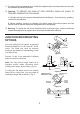
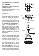
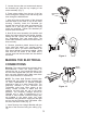
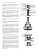
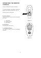
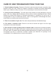
Table Of Contents

5
Figure 8
5. Loosen the two allen set screws and remove
the threaded pin from the top coupling of the
motor assembly. (Fig. 7)
6. Route wires exiting from the top of the fan
motor through the canopy cover and canopy and
then through the ball/downrod.
7. Align the holes at the bottom of the downrod
with the holes in the collar on top of the motor
housing. Carefully insert the threaded pin
through the holes in the collar and downrod. Be
careful not to jam the pin against the wiring
inside the downrod. Tighten the threaded pin
and two allen set screws.
8. Now lift the motor assembly into position and
place the hanger ball into the hanger bracket.
Rotate until the "Check Tab" has dropped into
the "Registration Slot" and seats firmly. The
entire motor assembly should not rotate if this is
done correctly.
9. Remove protective plastic sleeve from the
motor shaft and attach your wooden blades.
Ignore this step if you have metal blades, as
they should already have been installed. Make
sure that the set screw in the blade hub is
counter-sunk into the bore-hole into the shaft of
the motor.
Registration
slot
MAKING THE ELECTRICAL
CONNECTIONS
Warning: The power should have already been
disconnected. Follow the steps below to
connect the fan to your household wiring. Use
the wire nuts supplied with your fan. Secure the
wire nuts with electrical tape. Make sure there
are no loose strands or connections.
NOTE: The Hand Held Remote Control units
included with your ceiling fan are equipped with
16 code combinations to prevent possible
interference from or to other remote units. The
frequency switches on your Receiver and
Transmitter units have been preset at the
factory. Please re-check to make sure the
switches on both units are set to the same
positions. The frequency settings should be
changed only in case of interference or if a
second or more remote controlled ceiling fans
are installed in the same room. Any code
combination will operate the ceiling fan and light
as long as the Receiver and Transmitter units
are set to the same codes (Fig. 9)
1. Insert Receiver into Hanger Bracket with the
flat side of the Receiver facing the ceiling. (Fig.
10)
Figure 9
Figure 10
Receiver
Hanger
bracket