
User Manual

1/2
AtlasSound.com
TELEPHONE: (800) 876-3333
FAX (800) 765-3435
1601 JACK MCKAY BLVD.
ENNIS, TEXAS 75119 U.S.A.
©2016 Atlas Sound L.P. All Rights Reserved. Atlas Sound is a trademark of Atlas Sound L.P. All other trademarks are the property of their respective owners. All specs are subject to change without notice. ATS005237 RevC 3/16
Drop Tile Ceiling Installation
1. Remove 2' x 2' or 2' x 4' tile.
2. Align adjustable dual rail & C-ring assembly on rear of tile in desired position.
3. Using the template provided, mark the 7-
5
/8" cut out circle with marker and cut hole.
4. Affix C-ring assembly to rails using screws provided and position assembly on rear of ceiling tile. Replace tile in grid. Ensure formed ends of tile
bridge rails extend to T-bar tile support rails.
5. Bring service loop from rear of tile, through the tile bridge / C-ring to the access panel located on top of enclosure. Terminate the service loop to
Phoenix style connector provided (please note polarity).
6. Insert enclosure through front of tile then follow these steps for the 3 “T-Handle” / dog legs that comprise the Safety First Mounting System.
A. Disengage first “T-Handle” from baffle.
B. Pull “T-Handle” down carefully in a smooth continuous motion until the dog leg engages the C-ring.
C. Carefully push the “T-Handle” upwards until you can feel it disengage from the dog leg.
D. Rotate the “T-Handle” 90 degrees clockwise and align the locking tab with the horizontal slot in the speaker baffle.
E. Push the “T-Handle” into the slot until it clicks, indicating locked position.
F. Repeat steps A - E above for the remaining 2 “T-Handles” / dog legs.
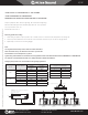
7. Adjust front mounted switch to desired power tap setting or 8Ω / 6Ω * (See important note regarding 8Ω / 6Ω operation).
8. Install press-fit grille into front bezel ring. Push baffle upwards until baffle is flush with bezel ring.
9. For safety and seismic considerations a suspension ring is integrated into the input panel section of unit. Atlas Sound strongly suggests that a
support wire be installed from this support point to a suitable anchor point above ceiling grid. In drop tile applications, this wire can usually be
installed from an adjacent tile access near speaker location.
Dry Wall (“Hard Deck”) Installation
1. Using the template provided, mark the 7-
5
/8" cut out circle with marker and cut hole.
2. Place tile bridge rails and C-ring through hole. Use V-shaped edge of C-ring to align tile bridge assembly above ceiling (alignment screws provided
are not required for this type of installation)
3. Bring service loop from rear of ceiling, through the Tile Bridge / C-ring to access panel located on the side of the enclosure. Terminate service loop
to Phoenix style connector provided (please note polarity).
4. Insert enclosure through front of tile then follow these steps for the 3 “T-Handle” / dog legs that comprise the Safety First Mounting System.
A. Disengage first “T-Handle” from baffle.
B. Pull “T-Handle” down carefully in a smooth continuous motion until the dog leg engages the C-ring.
C. Carefully push the “T-Handle” upwards until you can feel it disengage from the dog leg.
D. Rotate the “T-Handle” 90 degrees clockwise and align the locking tab with the horizontal slot in the speaker baffle.
E. Push the “T-Handle” into the slot until it clicks, indicating locked position.
F. Repeat steps A - E above for the remaining 2 “T-Handles” / dog legs.
5. Adjust front mounted switch to desired power tap setting or 8Ω/6Ω * (See important note regarding 8Ω/6Ω operation)
6. Install press-fit grille into front bezel ring. Push baffle upwards until baffle is flush with bezel ring.
7. For safety and seismic considerations a suspension ring is integrated into the input panel section of unit. Atlas Sound strongly suggests that a
support wire be installed from this support point to a suitable anchor point above ceiling grid.
FAP33T Strategy III Series
Install Sheet