
Owner's Manual


AtlasSound.com – 10 –
Owner’s Manual
AA100PHD
100W Mixer Amplifier
1601 Jack McKay Blvd. • Ennis, Texas 75119 U.S.A.
Telephone: 800.876.3333 • Fax: 800.765.3435
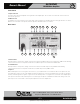
Rear Panel
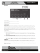
15. Multi Function DIP switch
Switch B
• DP SW #1 - Mute Receive Input 4 - When “ON”, Input 4 signal will be muted if a signal is present on Input 1 or if the Remote
Mute Terminals are shorted together.
• DP SW #2 - Mute Receive Input 3 - When “ON”, Input 3 signal will be muted if a signal is present on Input 1 or if the Remote
Mute Terminals are shorted together.
• DP SW #3 - Mute Receive Input 2 - When “ON”, Input 2 signal will be muted if a signal is present on Input 1 or if the Remote
Mute Terminals are shorted together.
• DP SW #4 - Input 2 Phantom Power 24VDC is active when Input 2 is set to Mic mode and the switch is in the ON position.
Note: Only use this feature if you are using condenser microphones, otherwise leave in the “OFF” position.
• DP SW #5 - When in the “MIC” position, Input 2 will accept microphone level signals; when in the “Line” position, Input 2 will
accept line level or telephone signals.
• DP SW #6 - Input 1 Phantom Power 24VDC is active when Input 1 is set to Mic mode and the switch is in the ON position.
Note: Only use this feature if you are using condenser microphones, otherwise leave in the “OFF” position.
• DP SW #7 - When in the “MIC” position, Input 1 will accept microphone level signals; when in the “Line” position, Input 1 will
accept line level or telephone signals.
• DP SW #8 - RIS (Remote Input Select) activates the RIS terminals when in the ON position. When the RIS is active, NO input
will be present at the amplifier output unless the RIS input port pins are shorted to ground. See RIS ports.
16. Amplifier Outputs
For loudspeaker connections, connect as follows or proceed to the setup section for typical wiring schemes.
• COM - Speaker common or negative connection
• 41 - Connect to direct coupled loudspeakers
• 25V - Connect to transformer coupled loudspeakers
• 70V - Connect to transformer coupled loudspeakers
17. Power Cord
Connect this grounded power cord to 120VAC circuits only. Serious damage may result otherwise.
18. Ground Terminal
Connect this terminal to electrical ground as required by local codes.
1
Input 4
Off
On
2
Mute RCV
Input 3
Off
On
3
Input 2
Off
On
Input 2 Input 1
RIS
4
Phantom
Off
On
5
Line
Mic
7
Line/Tel
Mic
6
Phantom
Off
On
8
On
Off