
Owner's Manual


– 9 – AtlasSound.com
Specifications are subject to change without notice.
Owner’s Manual
AA100PHD
100W Mixer Amplifier
1601 Jack McKay Blvd. • Ennis, Texas 75119 U.S.A.
Telephone: 800.876.3333 • Fax: 800.765.3435
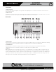
Rear Panel
12. Remote Level Control Port
Remote location of a level control can be accomplished via the Remote Level control port. You can control Input 1 or Inputs 2, 3, and
4. Connections to a 10K pot requires three conductors and a minimum of 22 gauge wire. The return ports can be paralleled together
if one pot is to control all inputs. The AAPHD series remote level design is based on 10VDC Return VCA type topology. Atlas Sound
accessory level controls WPD-RISRL or WPD-VC10K can be used to achieve this.
The remote level control ports are PRE Input Level Controls and PRE the Master Level on the front panel. Set the system’s maximum
levels using the amplifier input level controls and then use the remote potentiometer as an attenuator from the maximum levels set.
13. Pre Out
The PRE OUT RCA port is POST the preamp mix bus but PRE the Master Level. This feature is used in two applications.
A. Effects loop - Used in conjunction with the AMP IN connector, an effects loop can be created by connecting the PRE OUT
jack to a device such as an equalizer or DSP and then back out to the AMP IN connector.
B. Second Amplifier - If the amplifier output power is not enough, the mixer amp can be used as a preamp to feed a second
amplifier of choice. Note: The Master level will not be functional for the application.
14. Amp In
The AMP IN connector is useful for converting the AAPHD into a slave amp. When a line level signal is connected to this input, the
internal connection between the preamp and internal power amp is broken. Audio signals applied to this connector are POST tone
control and input level controls. The Master Level will function.
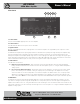
15. Multi Function DIP switch
Understanding the functionality of the DIP switches is key to maximizing the versatility of the AAPHD Series. When a switch is in the
up position, the function is “OFF or assigned to the feature stated”; when a switch is in the down position, the function is “ON or
assigned to the feature stated “.
Switch A
• DP SW #1 - Zone 2 Assign Input 4 - When “ON”, Input 4 signal will be routed to the Zone 2 Output terminals. The signal
routed is PRE the front panel level controls.
• DP SW #2 - Zone 2 Assign Input 3 - When “ON”, Input 3 signal will be routed to the Zone 2 Output terminals. The signal
routed is PRE the front panel level control.
• DP SW #3 - Zone 2 Assign Input 2 - When “ON”, Input 2 signal will be routed to the Zone 2 Output terminals. The signal
routed is PRE the front panel level control.
• DP SW #4 - Zone 2 Assign Input 1 - When “ON”, Input 1 signal will be routed to the Zone 2 Output terminals. The signal
routed is PRE the front panel level control.
Zone 2 Assign
1
Input 4
Off
On
2
Input 3
Off
On
3
Input 2
Off
On
4
Input 1
Off
On