
Owner's Manual


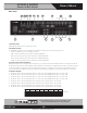
Table Of Contents
- Owner’s Manual
- Table of Contents
- Important Safety Instructions
- Introduction
- Key Features
- Applications
- Front Panel
- Rear Panel
- Installation
- Rack Mounting (Optional)
- Choose Input Wire and Connectors
- Choose Output Wire and Connectors
- Outputs
- Operation
- Measuring a Speaker System’s Impedance
- Measuring 25V/70.7V Distributed Speaker Systems
- Warranty

AtlasIED.com – 10 –
Specifications are subject to change without notice.
Owner’s Manual
AA120G & AA240G
Commercial Mixer Amplifier
1601 Jack McKay Blvd. • Ennis, Texas 75119 U.S.A.
Telephone: 800.876.3333 • Fax: 800.765.3435
Rear Panel
1. AC Power Inlet
Detachable IEC accepts US or Euro style power cords.
2. Amplifier Outputs
For loudspeaker connections, connect as follows or proceed to the setup section for typical wiring schemes.
• COM - Loudspeaker common or negative connection
• 8Ω - Connect to positive terminal on direct coupled loudspeakers
• 25V - Connect to positive terminal on transformer coupled loudspeakers
• 70V - Connect to positive terminal on transformer coupled loudspeakers
• 100V - Connect to positive terminal on transformer coupled loudspeakers
3. Inputs 1-4 Euro block Connectors
Balanced Microphone or Line level signals connect to the (+), (–), and (G) terminals. To select between Mic or Line input levels, refer to
the Switch A chart on the rear of the amplifier for feature assignment. If connecting an unbalanced line level input, tie (short) the (G) and
(–) terminals together for negative or ground connection and the positive or (+) signal to the (+) terminal on the amplifier input. If the
input is used in Mic mode, Phantom power for condenser type microphones is available in the DIP switch settings on the rear panel.
4. Switch A Settings
• DP SW #1 - When in the On (UP) position Input 4 is in Mic mode, OFF (DOWN) position Input 4 is in Line mode.
• DP SW #2 - When in the On (UP) position Input 3 is in Mic mode, OFF (DOWN) position Input 3 is in Line mode.
• DP SW #3 - When in the On (UP) position Input 2 is in Mic mode, OFF (DOWN) position Input 2 is in Line mode.
• DP SW #4 - When in the On (UP) position Input 1 is in Mic mode, OFF (DOWN) position Input 1 is in Line mode.
• DP SW #5 - When in the On (UP) position Input 4 Phantom power is present at the + & - terminals
• DP SW #6 - When in the On (UP) position Input 3 Phantom power is present at the + & - terminals
• DP SW #7 - When in the On (UP) position Input 2 Phantom power is present at the + & - terminals
• DP SW #8 - When in the On (UP) position Input 1 Phantom power is present at the + & - terminals
481012 1113 15 1614 5
1 2 79 63
1
Input 4
Mic
Line
2
Input 3
Mic
Line
3
Input 2
Mic
Line
4
Input 1
Mic
Line
5
Input 4
On
Off
6
Input 3
On
Off
7
Input 2
On
Off
Phantom
8
Input 1
On
Off
Switch A