
Owner's Manual


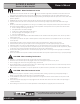


Table Of Contents
- Owner’s Manual
- Table of Contents
- Important Safety Instructions
- Introduction
- Key Features
- Applications
- Front Panel
- Rear Panel
- Installation
- Rack Mounting (Optional)
- Choose Input Wire and Connectors
- Choose Output Wire and Connectors
- Outputs
- Operation
- Measuring a Speaker System’s Impedance
- Measuring 25V/70.7V Distributed Speaker Systems
- Warranty

– 9 – AtlasIED.com
Specifications are subject to change without notice.
Owner’s Manual
AA120G & AA240G
Commercial Mixer Amplifier
1601 Jack McKay Blvd. • Ennis, Texas 75119 U.S.A.
Telephone: 800.876.3333 • Fax: 800.765.3435
Front Panel
1. Input Signal Presence/Clip Indicators
Green LED, one above each channel’s volume control, illuminates when input signal exceeds –40 dBu, and flashes brightly at threshold
of audible distortion.
2. Master Level Control
The Master Level control will raise or lower all the input channels together. A good starting point for setting gain structure is to set
the Master Level control at the 12:00 position, and then adjust the individual channels one at a time.
3. Output Signal Indicator
Green LED above master level control illuminates when any input signal exceeds –40 dBu.
4. Output Peak Indicator
Red LED above master output volume control will illuminate when the amp is -3dB below a clipping condition. This is caused by
excessively high input levels or when a Gain control is turned up too high. An occasional flash is OK.
5. Power Indicator
This LED illuminates Blue when the power switch is turned On.
6. Input Level Controls
The rotary control varies the amplitude of the signal fed to the amplifier input. Turn clockwise to increase and counter-clockwise to
decrease the signal level.
7. Tone Controls
Bass and Treble nondetented recessed potentiometers under master level control.
Bass ±10 dB at 100 Hz, Treble ±10 dB at 10 kHz.
8. Power Switch
This push switch (On/Off) supplies power to the mixer amplifier.
1 2
6
3 4
5
7 8