
Owner's Manual
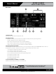

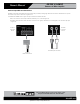


Table Of Contents

– 11 – AtlasIED.com
Specifications are subject to change without notice.
Owner’s Manual
AA35G & AA60G
Commercial Mixer Amplifier
1601 Jack McKay Blvd. • Ennis, Texas 75119 U.S.A.
Telephone: 800.876.3333 • Fax: 800.765.3435
Wire the System
Typical input and output wiring is shown in Figure 2.8.
INPUTS: For Input 1, connect a microphone or balanced line-level signal to the Input 1 balanced input. Set the Mic/Line switch (DIP
switch #1) accordingly. For the other inputs, connect unbalanced line-level signals to the RCA input connectors.
OUTPUTS: Maintain proper polarity (+/–) on amplifier output connectors.
Connect the Amplifier Output screw terminals to the loudspeaker loads. Use terminals marked COM and 70V or 100V for constant
voltage loudspeaker loads. Use terminals marked COM and 81 for an 81 loudspeaker.
Connect the COM terminal to loudspeaker negative (–) lead; connect one of the other terminals to loudspeaker positive (+) lead.
Cover the output connections with the supplied clear non-touch cover by sliding the cover on.
Phantom Power
Condenser microphones require phantom power to operate. If you are using a condenser microphone on Input 1, turn on DIP switch
#8 on the back of the mixer-amp. The microphone must be able to work on 15V phantom power, which the mixer amplifier’s mic input
connector provides.
Loudspeakers with 70V Transformers
CD Player
To Mic
Paging Mic
To Switch In Mic.
Switch Mutes Other Channels
Telephone System
Interface/PBX
In-Ceiling
Loudspeaker
5-Terminal Removable
Barrier Block (Euroblock)
Figure 2.8
Input-Output Wiring
IN
Satellite Receiver