
Owner's Manual


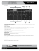
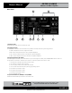

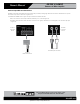
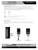
Table Of Contents

– 7 – AtlasIED.com
Specifications are subject to change without notice.
Owner’s Manual
AA35G & AA60G
Commercial Mixer Amplifier
1601 Jack McKay Blvd. • Ennis, Texas 75119 U.S.A.
Telephone: 800.876.3333 • Fax: 800.765.3435
Rear Panel
1. AC Power Inlet
Detachable IEC accepts US or Euro style power cords.
2. Amplifier Outputs
For loudspeaker connections, connect as follows or proceed to the setup section for typical wiring schemes.
• COM - Loudspeaker common or negative connection
• 81 - Connect to positive terminal on direct coupled loudspeakers
• 70V - Connect to positive terminal on transformer coupled loudspeakers
• 100V - Connect to positive terminal on transformer coupled loudspeakers
3. Amp Configuration DIP Switch
Understanding the functionality of the DIP switches is key to maximizing the versatility of the AA35G/AA60G. When a switch is in
the up position, the function is “ON”and when a switch is in the down position, the function is “OFF”.
1. On: Sets CH1 to Mic Input. Off: Sets CH1 to Line Input.
2. On: Sets CH1 to Normal mode (no priority).
3. On: CH1 priority contact closure mutes other channels.
4. On: CH1 VOX mutes other channels by sensing signal through Input 1.
5. On: Routes CH1 to Zone 2 output.
6. On: Routes CH2 to Zone 2 output.
7. On: Routes CH3 to Zone 2 output.
8. On: 15V phantom power.
4. Input Connectors 2-3 (AA35G) or 2-4 (AA60G)
Unbalanced line-level RCA-type connectors, summed to mono.
1 92
4
5 6
3
87