
Owner's Manual


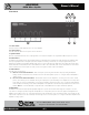
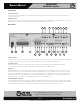
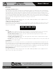
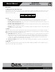
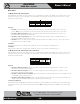
Table Of Contents
- Owners Manual
- Table of Contents
- Features
- Applications
- Parts & Controls
- Using the PHD Mixer Amplifier Diagnostic System
- How To Trouble Shoot Your Speaker System If The Limit LED Is Illuminating
- How To Trouble Shoot Your Speaker System If The Limit LED Is Illuminating
- Connecting a Remote Level Control with Remote Input Select
- Wiring the AAPHD Series Amplifier
- Level Control Security Cover Option
- Block Diagram
- Specs
- Spec Sheet
- Warranty

– 7 – AtlasSound.com
Specifications are subject to change without notice.
Owner’s Manual
AA400PHD
400W Mixer Amplifier
1601 Jack McKay Blvd. • Ennis, Texas 75119 U.S.A.
Telephone: 800.876.3333 • Fax: 800.765.3435
Front Panel
7. Input 1-6 Level
The rotary control varies the amplitude of the signal fed to the amplifier input. Turn clockwise to increase and counter-clockwise to
decrease the signal level.
8. Master Level
The Master Level control will raise or lower all the input channels together. A good starting point for setting gain structure is to set the
Master Level control at the 12:00 position, and then adjust the individual channels one at a time.
Rear Panel
1. Bass Control
Normally set at the 12:00 position, rotating clockwise will increase (boost) bass frequencies to a maximum of +6dB at 100Hz. Rotating
counter-clockwise from the 12:00 position will decrease (cut) bass frequencies to a maximum of -6dB at 100Hz.
2. Treble Control
Normally set at the 12:00 position, rotating clockwise will increase (boost) treble frequencies by +6dB at 10kHz. Rotating
counter-clockwise from the 12:00 position will decrease (cut) treble frequencies by -6dB at 10kHz.
3. Input 1
Balanced Microphone or Line level signals connect to the (+), (-), and (G) terminals. To select between Mic or Line input levels, refer
to the DIP switch chart on the rear of the amplifier for feature assignment. If connecting an unbalanced line level input, tie (short) the
(G) and (-) terminals together for negative or ground connection and the positive or (+) signal to the (+) terminal on the amplifier input.
If the input is used in Mic mode, Phantom power for condenser type microphones is available in the DIP switch settings on the rear
panel. Input 1 level control located on the front panel adjusts the levels to the amplifier mix.
4. Remote Mute Connector
Shorting the Remote Mute terminals, (G) to (M), will mute the inputs that are assigned to receive the mute command. When an input
is set to Mute Receive via the corresponding DIP switch, the input associated to the switch will be muted when terminals (G) and (M)
are shorted together. This connection is usually done via remote switch on a microphone. Input 1 cannot be muted.
1010 889911 1312
5171424 25 23 22 31 2 20 7
461521 16 1819